Available with Production Mapping license.
Map production may require extending a standard GIS database with cartographic data in the form of additional attributes and features. GIS models the real world as a series of features with attributes. Cartography visualizes real-world features in a simplified presentation. Map production in ArcGIS for Desktop uses additional cartographic data to help automate and improve the map production process.
Cartographic features can include grids and graticules layers and new or generalized data displayed in the map. The Grids and Graticules tools are used to produce grids that contain geographic location indicators based on user-specified shapes, scales, coordinate systems, and units. For this exercise, you will modify an existing grid XML file and create new grids and graticules layers.
A number of standard grid templates are included in ArcGIS for Desktop. In this exercise, you will work with the Quad_24K_NAD83.xml file, generating the grid features for the Austin East map document and modifying how the grid is displayed.
Exercise 2a: Generating grids and graticules layers
For this exercise you will use the Make Grids and Graticules Layer geoprocessing tool to generate the layers as well as the Grids and Graticules Designer window to modify the grids components.
- If necessary, start ArcMap and open the Austin East map.
- In the Product Library window, check the check box next to the Austin East product.
- Right-click the Austin East product and click Zoom To.
The data frame zooms to match the AOI in the product library.
- Right-click the Austin East product and click Select.
The Austin East AOI feature is selected in the map.
- To ensure that the map is in data view, on the main menu, click View > Data View.
- If necessary, click the ArcToolbox button
 on the Standard toolbar.
 - Expand the Cartography Tools toolbox.
- Expand the Grids and Graticules toolset.
- Double-click the Make Grids and Graticules Layer tool.
The Make Grids and Graticules Layer dialog box appears.
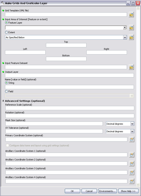
- Click the Open button
 next to the Grid Template (XML file) text box.
The Open dialog box appears.
- Navigate to the GridTemplates directory in the ArcGIS for Desktop installation location.
The default path is C:\Program Files\ArcGIS\Desktop10.3\GridTemplates.
- Select the Quad_24K_NAD83.xml file.
- Click Open.
- Click the Feature Layer drop-down arrow and choose Topographic Maps::Texas::Travis County::Austin East.
- Click the Open button
 next to the Input Feature Dataset text box.
The Input Feature Dataset dialog box appears.
- Select the Grids feature dataset in the Austin.gdb geodatabase.
The Austin.gdb geodatabase is located in the directory where the tutorial data was copied.
- Click Add.
- Leave the remaining default parameters and click OK.
A grid is generated over the extent of the selected Austin East feature and added to the map.
- If necessary, click Close on the Make Grids and Graticules Layer dialog box.
- Click the Close button
 in the upper-right corner of the ArcToolbox window.
The grid layers are generated over the extent of the selected feature. The grids and graticules layers are added to the table of contents in a group called Quad_24K_NAD83.
- On the main menu, click Customize > Toolbars > Production Cartography.
- Click the Grids and Graticules Designer window button
 on the Production Cartography toolbar.
The Grids and Graticules Designer window appears.
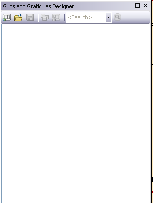
- Right-click in the Grids and Graticules Designer window and click Refresh.
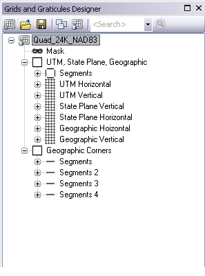
The structure of the grid is added to the Grids and Graticules Designer window.
- Click the Zoom In tool
 on the Tools toolbar.
 - Draw a box to zoom in to the lower-right corner of the Austin East feature.
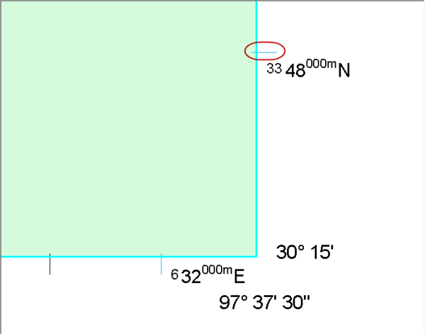
Notice that some of the ticks are displayed in blue.
Exercise 2b: Modifying a grid XML
You can modify the format and structure that grids and graticules layers will have using the Grids and Graticules Designer window. The Grids and Graticules Designer window allows you to add, remove, and modify components in the grid, such as the format of annotation or the spacing of grid lines. Normally, the grid template XML should be configured for the cartographic specifications that the product will use. This configuration is typically done by a project or technical lead team member who will share this grid definition with the rest of the team. In this exercise, you will perform the role of the technical lead who makes modifications to the existing grid definition. The definition of grids and graticules layers are stored in a grid XML file.
The tree view in the Grids and Graticules Designer window shows all of the components of your grid. The graphic that appears next to the node in the tree indicates the component type for that item.
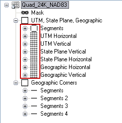
- If necessary, expand the UTM, State Plane, Geographic neat line node.
- Expand the Segments segment node.
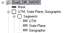
- Double-click the UTM ticks node.
The Tick Properties window appears. This window is used to customize the properties of the grid.
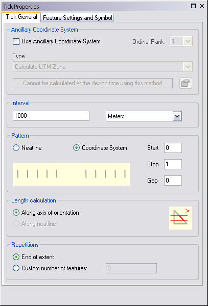
- Type 500 in the Interval text box.
This property changes how often the ticks are displayed. Now, instead of displaying ticks every 1,000 meters, the ticks will be displayed twice as often, every 500 meters.
- Click the Feature Settings and Symbol tab.
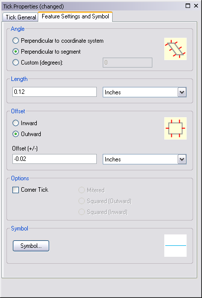
- Click Symbol at the bottom of the Feature Settings and Symbol tab.
The Representation Rule Selector dialog box appears. This dialog box allows you to modify the symbol that will be used to display this tick component.
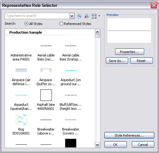
- Click Properties.
The Representation Rule dialog box appears.
- Click the blue cell next to the Color property.
A color pallette appears.
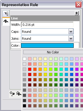
- Select a red color from the color pallette.
- Click OK.
- Click OK.
The red symbol is now set for this tick and will be applied the next time you generate the grid.
- Click the Close button
 to close the Tick Properties window.
Exercise 2c: Updating grids and graticules layers
Now that you have modified the grid XML, you can create the grids and graticule layers. You will also test the new grid design to ensure it has the correct values and settings before you share the XML with other users.
- Ensure that the Austin East feature you selected in Exercise 2a is selected.
- Click the Set Feature Dataset button
 at the top of the Grids and Graticules Designer window.
The Dataset Location for Grid dialog box appears.
- Select the Grids feature dataset in the Austin.gdb geodatabase.
The Austin.gdb geodatabase is located in the directory where the data was copied.
- Click OK.
The Grids and Graticules Designer window appears.
- Click OK to overwrite the grid in this feature dataset.
- Click the Create button
 at the top of the Grids and Graticules Designer window.
A warning message appears indicating that the grid will be updated.
- Click OK.
The grid layers are generated over the extent of the selected feature. The grids and graticules layers are added to the table of contents in a group called Grids_Quad_24K_NAD83_Quad_24K_NAD83.
- If necessary, zoom in to the lower-right corner of the Austin East feature.
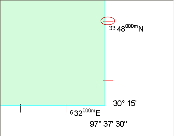
Notice that the ticks are now displayed in red and new ticks appear. The grid has the correct look and can now be saved and shared with other users.
- Click the Save as button at the top of the Grids and Graticules Designer window.
The Save As dialog box appears.
- Navigate to the directory where the data has been copied.
- In the File name text box, type New_QUAD_24K.
- Click Save.
- In the Table Of Contents window, right-click the Quad_24K_NAD83 layer and click Remove.
This removes the original grid that was created with the geoprocessing tool, as a new layer was also created and added to the table of contents (Grids_Quad_24K_NAD83_Quad_24K_NAD83) with the Grids and Graticules Designer.
- Click the Close button
 in the upper-right corner of the Grids and Graticules Designer window.
 - In the Product Library window, right-click Austin East and click Zoom to.
The map display is zoomed to the extent of the Austin East map.
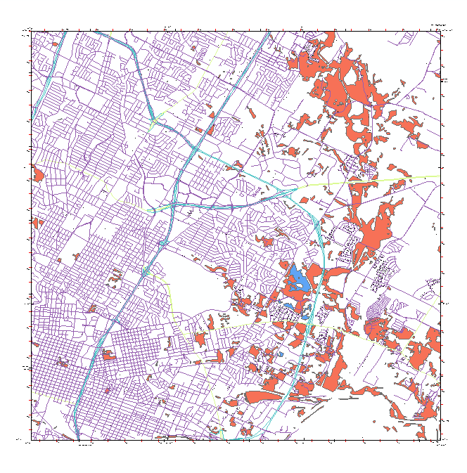
- Click the Austin East product to turn off the display of the Austin East feature.
- Save your changes to the map document.
In this exercise, you began to customize the map by creating a grid using the Make Grids and Graticules Layer geoprocessing tool. You have also learned how to modify the format and structure of the grids and graticules layer using the Grids and Graticules Designer to add, remove, and modify components of the grid. In Exercise 3: Working with visual specifications, you can learn how to apply representations configured using visual specifications as well as customize visual specification rules.