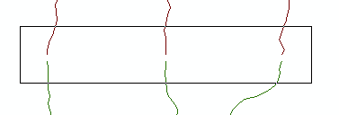
The edgematching process aligns features along the edge of one layer to features of an adjoining layer. It is mainly used when you want to merge separate adjacent layers, such as soils or contours sheets, and you need to ensure the features from those layers will meet at the join. The layer with the less accurate features is typically adjusted, while the adjoining layer is used as the control. Displacement links are used to adjust vertices or the ends of line features to the corresponding locations in the adjoining control layer.
To support the edgematching process, you can use the Edge Match tool on the Spatial Adjustment toolbar to quickly create links between features that are supposed to adjoin along a sheet edge.
The Edge Match tool
The Edge Match tool  allows you to create displacement links that connect the edges of two adjacent layers. To use this tool effectively, you need to first setup the parameters for the tool's properties, available from the Edge Match tab of the Adjustment Properties dialog box, and set an appropriate snapping tolerance. Once you have set these, use the tool to drag a box around the features you want to edgematch. This creates displacement links from the ends or vertices of features in the layer to be adjusted to the ends or vertices of features in the control layer that fall within the snapping tolerance distance. The only features that are adjusted are those that have displacement links at these locations.

You can use additional properties to enhance the link-creation process, such as specifying one link per destination point and preventing duplicate links. You can also use attributes to assist with the creation of links by ensuring they connect to features that share common attribute values such as road names and pipeline widths.
These properties, combined with the proper snapping settings, help ensure an accurate edgematch.