Available with Standard or Advanced license.
Geometric network features store various mechanisms and behaviors that maintain the topological connectivity between them. ArcMap is tightly integrated with the geodatabase when it comes to editing network features.
For overview information on geometric networks, how you would use them, and some of their associated terms, see What are geometric networks?
Creating connectivity
Topological connectivity in a network feature class is based on geometric coincidence. If a junction is added along an edge, or one edge is added along another edge, they will become topologically connected to one another.
By using the ArcMap snapping environment, you can create new edge and junction features on the fly while maintaining network connectivity. The ArcMap snapping functionality guarantees geometric coincidence when adding new network features along existing network features.
It is critical to maintain connectivity, since your tracing and other networking tasks won't work as expected without it.
Since connectivity is based on geometric coincidence, establishing connectivity with coincident features will be indeterminate. For example, if a junction is added along two coincident edges, the junction can connect to either edge. As such, coincident features are not supported within the geometric network.
Simple and complex edges
An edge in a geometric network can be either simple or complex. A simple edge in a geometric network has a 1–1 relationship with edge elements in the logical network. A complex edge has a 1–M relationship with edge elements in the logical network. So one complex edge in the geometric network can represent multiple edges in the logical network.
If you snap a junction or edge along a simple edge, the edge being snapped to is split both in the logical network and in the geometric network, giving you two edge features. If you snap a junction or an edge along a complex edge, that edge is split in the logical network but remains a single feature in the geometric network. It will remain a single feature; however, a new vertex is created at the point where the new junction or edge connects to it.
Default junctions
When you snap an edge to another edge where there is no junction, a junction is automatically inserted to establish connectivity. If a default junction type has been specified as part of the connectivity rules for the network, that default junction type is used. If there is no edge-edge rule between these edge types, an orphan junction is inserted, which is stored in the <network>_Junction feature class.
Similarly, if you create a new edge in the network that is not snapped to an existing junction or edge at both ends, a junction is automatically created and connected to the free end of the new edge. If there is a connectivity rule in place that defines a default junction type for the type of edge that is being added, that default junction type is the junction that is added to the free end of the new feature. If an edge type does not have a default junction type associated with it through a connectivity rule, an orphan junction is inserted, which is stored in the <network>_Junction feature class.
Junction subsumption
When you snap a junction to an existing orphan junction, the orphan junction is subsumed by the new junction. That is, the orphan junction is deleted from the network and the new junction is inserted in its place. All network connectivity is maintained. Orphan junctions cannot subsume other orphan junctions. When a junction is snapped to another junction other than an orphan junction, subsumption does not occur and the newly added junction is not connected.
When you create a new edge feature in the network that has an end that does not connect to anything, and there is not a connectivity rule stating what type of junction to put at its free end, the network orphan junction type is inserted. This orphan junction can be replaced by snapping another junction to it.
Moving existing geometric network features
When a network edge or junction is moved, the network features to which it is connected respond by stretching and adjusting themselves to maintain connectivity. When you move a network feature and snap it to another network feature, the features may become connected (as illustrated in the following section, "Connectivity models").
Connectivity models
Edit operations that involve adding, deleting, moving, and subsuming network features can all affect the connectivity of a geometric network. Each type of operation may or may not create connectivity, depending on the type of network features involved. If connectivity is not created, it can be established by using the Connect command.
The following set of diagrams illustrates various editing scenarios and their resulting connectivity or lack thereof. In these diagrams, use the key below to identify what types of features are depicted in each scenario: 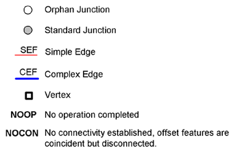
Stretching and moving
When stretching or moving junctions, any edges connected to them rubber-band to remain connected. When you snap these junctions to other network features, the following illustration summarizes the network connectivity that results: 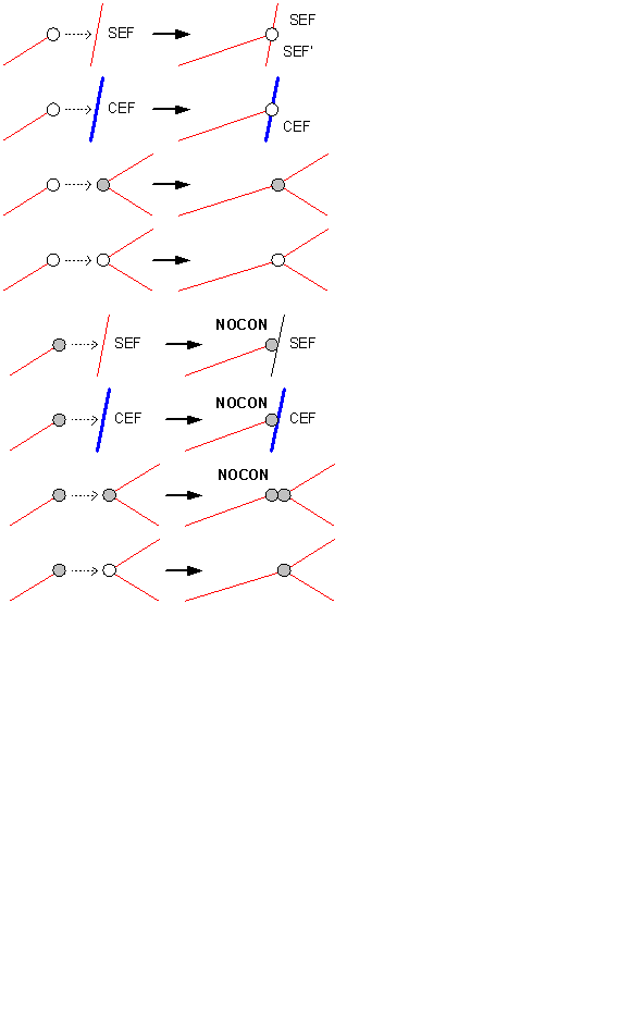
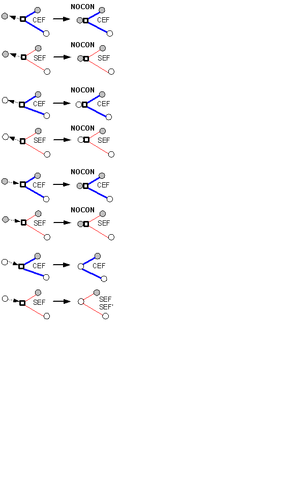
Deleting
Deleting network features can affect those features connected to them. When you delete an edge feature, the edge is physically deleted from the geometric network and logically deleted from the logical network; however, its connected junction features will not be deleted. When deleting junction features, if the junction being deleted is not of an orphan junction type, it will not be physically deleted from the geometric network. Rather than being deleted, the junction will become an orphan junction. When you delete an orphan junction, it is physically deleted from the geometric network. When this happens, depending on what type it is and how many edges are connected to it, some edges may also be deleted. The following illustration summarizes the results of deleting network junctions: 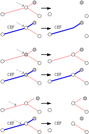
Disconnecting features
The following illustration summarizes how connectivity is affected when disconnecting network edge features and junction features using the Disconnect command in ArcMap: 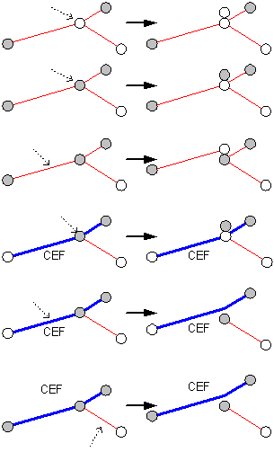
Connecting features
The following illustration summarizes how connectivity is affected when connecting network features using the Connect command in ArcMap: 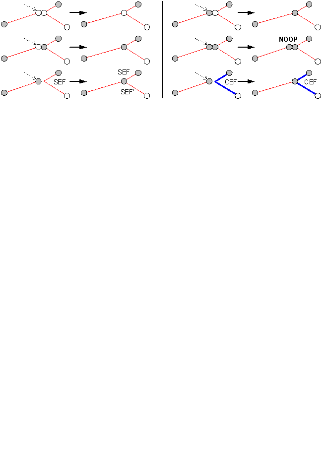
Creating new network features
When creating new network features and snapping them to other network junctions and edge features, the resulting connectivity and the effects on the features you connect them to are summarized below: 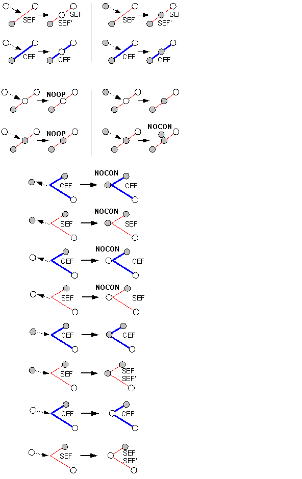
Repairing geometric network connectivity
Connectivity between network features is maintained on the fly as you create, delete, and modify network features. In some circumstances, the association between certain network features and their logical elements may become out of sync. This can happen, for example, when using a custom tool that does not correctly handle aborting edit operations.
This kind of network inconsistency is usually localized to a collection of features in the network. You will be able to see what features have inconsistent connectivity in three ways:
- When moving a network feature, if stretching does not occur with other network features it is connected to and the edit operation fails, the feature has inconsistent connectivity.
- Reconciling a version with inconsistent network features will result in an error (see Resolving conflicts interactively to learn more about reconciling versions).
- Using one of the network connectivity verification tools or commands described below will reveal inconsistent connectivity.
The Rebuild Connectivity tool deletes and rebuilds connectivity for a set of network features that are contained within or intersect a user-defined extent by re-creating their logical elements. Connectivity is established based on geometric coincidence using the same rules as described in About creating geometric networks.
The Repair Connectivity command in ArcMap repairs the connectivity within an entire geometric network or the connectivity within the currently edited version in ArcSDE. The Repair Connectivity command can be used if a large number of features have inconsistent connectivity or the features extend across a large part of the network.
In addition to the Rebuild Connectivity tool and Repair Connectivity command, ArcMap also contains a set of tools and commands for identifying network features with either inconsistent connectivity or illegal network geometry. These are the Network Build Errors, Verify Network Connectivity, and Verify Network Geometry commands and the Verify Network Connectivity and Verify Network Geometry tools. These tools and commands can be accessed from the Geometric Network Editing toolbar.
For information on the Network Build Errors command, see About creating geometric networks.
Performance considerations
Connectivity is established for new network features based on geometric coincidence. When you add or move a feature in a network, each feature class in the network must be analyzed so connectivity can be established. Performing a spatial query against each network class will determine whether the new feature or moved feature is coincident with other network features at any point.
If the network is in an ArcSDE geodatabase, analyzing for connectivity requires a number of spatial queries against the server. Using the feature cache can make your edits many times faster than without the cache, and it does not require as much of the server.