- Engine
- ArcGIS for Desktop Basic
- ArcGIS for Desktop Standard
- ArcGIS for Desktop Advanced
- Server
Additional library information: Contents, Object Model Diagram
The Display library contains objects used to display geographic information system (GIS)data. In addition to the main display objects that are responsible for the output of the image, the library contains objects that represent symbols and colors that control the properties of entities drawn on the display. The library also contains objects that provide the user with visual feedback when interacting with the display.
See the following sections for more information about this namespace:
Display
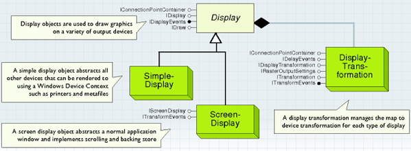
The Display object abstracts a drawing surface. A drawing surface is any hardware device, export file, or memory stream that can be represented by a Windows Device Context. Each display manages its own Transform object that handles the conversion of coordinates from real world space to device space and back. The following standard displays are provided:
- ScreenDisplay abstracts a normal application window and implements scrolling and backing store (multiple backing layers are possible).
- SimpleDisplay abstracts all other devices that can be rendered to using a Windows Device Context, such as printers, metafiles, bitmaps, and secondary windows.
The display objects allow application developers to draw graphics on a variety of output devices. These objects allow you to render shapes stored in real world coordinates to the screen, the printer, and export files. Application features, such as scrolling, backing store, print tiling, and printing to a frame can be easily implemented. If some desired behavior is not supported by the standard objects, custom objects can be created by implementing one or more of the standard display interfaces. See the following illustration:
In general, you must have a device context (DC) to do any drawing in windows. The handle device context (HDC) defines the device that you are drawing on. Some example devices are windows, printers, bitmaps, and metafiles. In ArcObjects, a display is a wrapper for a windows device context.
Use a SimpleDisplay coclass when you want to draw on a printer, export file, or simple preview window. Specify the HDC that you want to use to StartDrawing. This tells the display which window, printer, bitmap, or metafile to draw on. The HDC is created outside of ArcObjects using a Windows Graphical Device Interface (GDI) function call.
Use a ScreenDisplay coclass when you want to draw maps to the main window of your application. This coclass handles advanced application features, such as display caching and scroll bars. Specify the HDC for the associated window to StartDrawing. Normally, this is the HDC returned when you call the Windows GDI BeginPaint function in your application's WM_PAINT handler. Alternatively, you may specify 0 as the HDC parameter for StartDrawing, and an HDC for the associated window is automatically created. Normally, a ScreenDisplay uses internal display caches to boost drawing performance. During a drawing sequence, output is directed to the active cache and once per second, the window (that is, the HDC specified to StartDrawing) is progressively updated from the active cache. If you want to prevent progressive updates (that is, if you want to update the window once when drawing has completed), specify the recording cache HDC; IScreenDisplay.getCacheMemDC(esriScreenRecording) to StartDrawing.
Use the IDisplay interface to draw points, lines, polygons, rectangles, and text on a device. Access to the display object's DisplayTransformation object is provided by this interface. See the following illustration:
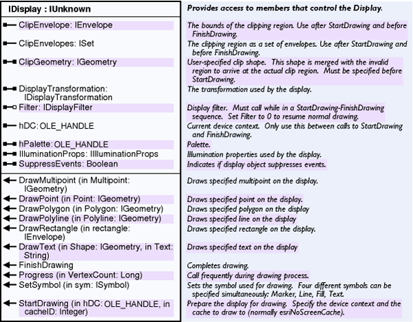
- DisplayTransformation—This object defines how real-world coordinates are mapped to a output device. Three rectangles define the transformation. The Bounds specifies the full extent in real-world coordinates. The VisibleBounds specifies the visible extent. The DeviceFrame specifies where the VisibleBounds appears on the output device. Since the aspect ratio of the DeviceFrame may not always match the aspect ratio of the specified VisibleBounds, the transformation calculates the actual visible bounds that fits the DeviceFrame. This is called the FittedBounds and is in real-world coordinates. All coordinates can be rotated about the center of the visible bounds by setting the transformation's Rotation property.
Display caching
The main application window is controlled by a view (IActiveView). There are currently two view coclasses implemented: Map (data view) and PageLayout (layout view). ScreenDisplay makes it possible for clients to create caches (a cache is a device dependent bitmap). When a cache is created, the client gets a cacheID. The ID is used to specify the active cache (last argument of StartDrawing, where output is directed), invalidate the cache, or draw the cache to a destination HDC. In addition to dynamic caches, the ScreenDisplay also provides a recording cache that accumulates all drawing that happens on the display. Clients manage recording using the StartRecording and FinishRecording methods.
To see how caches are implemented in ArcObjects, the Map coclass will be examined. In the simplest case, the Map creates one cache for all layers, another cache if there are annotation or graphics, and a third cache if there's a feature selection. It also records all output. In addition to these caches, it's also possible for individual layers to request a private cache by returning true for their cached property. If a layer requests a cache, the Map creates a separate cache for the layer and groups the layers above and below it into different caches. The IActiveView.partialRefresh method uses the cache layout to invalidate as little as possible so you can draw as much as possible from the cache. Given these caches, all of the following scenarios are possible:
- Use the recording cache to redraw when the application is moved or exposed or when drawing editing rubberbanding. This is very efficient since only one BitBlt is needed.
- Select a new set of features and invalidate only the selection cache. Features draw from cache. Graphics and annotation draw from cache. Only the feature selection draws from scratch.
- Move a graphic element or annotation over features. Only invalidate the annotation cache. Features draw from cache and feature selection draws from cache. Only the annotation draws from scratch.
- Create a tracking layer. Always return true for its cached property. To show vehicle movement when new Global Positioning System (GPS) signals are received, move the markers in the layer and only invalidate the tracking layer. All other layers draw from cache. Only the vehicle layer draws from scratch. This makes it possible to animate a layer.
- Create a basemap by moving several layers into a group layer and setting the group layer's cached property to true. Now you can edit and interact with layers that draw on top of the basemap without having to redraw the basemap from scratch.
- The concept of a display filter allows raster operations to be performed on any kind of layer including feature layers that use custom symbols. It will be possible to create a slider dialog that attaches to a layer. It sets the layer's cached property to true and uses a transparency display filter to interactively control the layer's transparency using the slider. Other display filters can be created to implement clipping, contrast, brightness, and so on.
Recording cache
The ScreenDisplay can record what gets drawn. Use startRecording() and stopRecording() to let the display know what should be recorded. Use drawCache(esriScreenRecording) to display what was recorded. Use getCacheMemDC(esriScreenRecording) to get a handle to the memory device context for the recording bitmap. This functionality has the following uses:
- Implement a single bitmap backing store by drawing a sequence. See the following code example:
IScreenDisplay screenDisplay;
MapControl mapControl;
boolean isCacheDirty = screenDisplay.isCacheDirty((short)
    esriScreenCache.esriScreenRecording);
if (isCacheDirty){
    screenDisplay.startRecording();
    screenDisplay.startDrawing(mapControl.getHWnd(), (short)
        esriScreenCache.esriNoScreenCache);
    drawContents();
    screenDisplay.finishDrawing();
    screenDisplay.stopRecording();
}

else{
    screenDisplay.drawCache(mapControl.getHWnd(), (short)
        esriScreenCache.esriScreenRecording, null, null);
}
- Clients can use allocated display caches (created with IScreenDisplay.addCache) to cache different phases of their drawing while still having a single bitmap (the recording) to use for quick refreshes. You can access the recording bitmap while drawing to implement advanced rendering techniques, such as translucency.
Caveats
If any part of your map contains transparency, it affects how things get refreshed. When a transparent layer draws, everything below it becomes part of the layer's rendering. As a result, the transparent layer must redraw from scratch each time something below it changes.
Text also has transparency if the anti-aliasing setting is turned on in Microsoft Windows. This means the text uses the layers that draw below it to carry out the anti-aliasing (the edges of the text are blended into the background). As a result, the annotation or auto-labels must draw whenever a layer changes.
Caching layers
Set the cached flag on the layers you want to have their own display cache and reactivate the view. See the following code example:
[Java]
public void enableLayerCaches(MapBean map){
    try{
        for (int i = 0; i < map.getLayerCount(); i++)
            map.getLayer(i).setCached(true);
        //Pass the values as needed.
        //Reactivate the display.
        map.getActiveView().deactivate();
        map.getActiveView().activate(map.getHWnd());
        map.getActiveView().refresh();
    }
    catch (Exception e){
        e.printStackTrace();
    }
}
Rotation
Understanding how rotatation is implemented in display objects is important since it affects all displayed entities. Rotation happens below the transformation level so clients of DisplayTransformation always deal with unrotated shapes. For example, when you get a shape back from one of the transform routines, it is in unrotated space. Also, when you specify an extent to the transform, the extent is also in unrotated space. When working with polygons, everything works. When working with envelopes, things are more complicated because rotated rectangles cannont be represented. This is best shown with the following examples:
- Getting a rectangle from the transform—For example, if you want a rectangle representing the client area of the window; since the user is seeing rotated space on the display, it's not possible to represent the requested area as an envelope. The four corners of the rectangle have unique x,y values in map space. The internal representation of the Envelope coclass assumes shared x,y values for the sides. As a result, the envelope returned by DisplayTransformation.FittedBounds is not what you want because a rectangular polygon is needed to accurately represent the client area in unrotated map space. Currently there's a bug that causes FittedBounds to return the same envelope that is returned when there is no rotation. When this is fixed, it should return a slightly expanded envelope as you expected. Most clients avoid using an envelope when there is rotation and implement code to find the rectangular polygon that matches a rectangle on the user's display. See the following code example:
inline void ToUnrotatedMap(const RECT & r, IGeometry * pBounds,
    IDisplayTransformation * pTransform){
    WKSPoint mapPoints[5];
    POINT rectCorners[4] = {
        {
            r.left, r.bottom
        }
        , {
            r.left, r.top
        }
        , {
            r.right, r.top
        }
        , {
            r.right, r.bottom
        }
    };
    pTransform -  > TransformCoords(mapPoints, rectCorners, 4, esriTransformToMap |
        esriTransformPosition);
    // Build polygon from mapPoints.
    mapPoints[4] = mapPoints[0];
    IPointCollectionPtr(pBounds) -  > SetWKSPoints(5, mapPoints);
    ITopologicalOperator2Ptr(pBounds) -  > put_IsKnownSimple(VARIANT_TRUE);
}
- Specifying a rectangle to the transform—Remember that the client needs to work in unrotated space and let the transform handle the rotation before displaying. When dragging a zoom rectangle, the user sees rotation space. The rectangle being dragged is in rotation space. The tool uses code similar to the preceding code to create a rectangular polygon representing the area selected by the user. The tool needs to convert the rectangle to unrotated space before specifying it to the transform. The following code example shows how this is done (pRotatedExtent is a rectangular polygon that exactly matches the rectangle dragged by the user):
IArea area = (IArea)rotatedExtent;
IPoint center = area.getCentroid();
ITransform2D transform = (ITransform2D)rotatedExtent;
transform.rotate(center, 45);
IEnvelope newExtent = rotatedExtent.getEnvelope();
Refreshing versus invalidation
To cause a display to redraw, call the Invalidate routine; however, most clients never use IScreenDisplay.Invalidate because if there is a view being used in your application, that is, the Map or PageLayout coclass, use the view for refreshing the screen (Refresh, PartialRefresh). The view manages the display's caches and knows the best way to carry out invalidation. Call PartialRefresh using the most specific arguments possible. Also, only call Refresh when absolutely necessary since this is a very time consuming operation.
-
One stop invalidation—To allow views (Map and PageLayout) to completely manage display caching, all invalidation must go through the view. Calling IActiveView.Refresh always draws everything and is very inefficient. The PartialRefresh method should be used whenever possible. It lets you specify what part of the view to redraw and allows the view to work with display caches that allows drawing to be quick and efficient. See the following table:
|
Draw phase
|
Map
|
PageLayout
|
|
esriViewBackground
|
unused
|
page/snap grid
|
|
esriViewGeography
|
layers
|
unused
|
|
esriViewGeoSelection
|
feature selection
|
unused
|
|
esriViewGraphics
|
labels/graphics
|
graphics
|
|
esriViewGraphicSelection
|
graphic selection
|
element selection
|
|
esriViewForeground
|
unused
|
snap guides
|
The following table shows example calls to the partial refresh method (notice the use of optional arguments):
|
Action
|
Method call
|
|
Refresh layer
|
map.partialRefresh(esriViewDrawPhase.esriViewGeography, layer,null);
|
|
Refresh all layers
|
map.partialRefresh(esriViewDrawPhase.esriViewGeography, null, null);
|
|
Refresh selection
|
map.partialRefresh(esriViewDrawPhase.esriViewGeoSelection, null, null);
|
|
Refresh labels
|
map.partialRefresh(esriViewDrawPhase.esriViewGraphics, null, null);
|
|
Refresh element
|
layout.partialRefresh(esriViewDrawPhase.esriViewGraphics, element, null);
|
|
Refresh all elements
|
layout.partialRefresh(esriViewDrawPhase.esriViewGraphics, null, null);
|
|
Refresh selection
|
layout.partialRefresh(esriViewDrawPhase.esriViewGraphicSelection, null, null);
|
Invalidating any phase will cause the recording cache to be invalidated. To force a redraw from the recording cache, use the following code example:
screenDisplay.invalidate(null, false, esriScreenCache.esriNoScreenCache)
Display events
This section describes the events that are fired when a map draws. To provide better insight into drawing events, drawing order, and display caching are discussed as well.
Drawing order
To better understand the events that are fired when a map draws, the following describes the order that objects are drawn for each kind of view.
-
Map (data view)—The following Map class drawing order table shows top to bottom order; each item is drawn above the items below it:
|
Object
|
Phase
|
Cache
|
|
Graphic selection
|
esriViewForeground
|
none
|
|
Clip border
|
esriViewForeground
|
none
|
|
Feature selection
|
esriViewGeoSelection
|
selection
|
|
Auto labels
|
esriViewGraphics
|
annotation
|
|
Graphics
|
esriViewGraphics
|
annotation
|
|
Layer annotation
|
esriViewGraphics
|
annotation
|
|
Layers
|
esriViewGeography
|
layer or layers
|
|
Background
|
esriViewBackground
|
bottom layer
|
-
PageLayout—The following PageLayout class drawing order table shows top to bottom order; each item is drawn above the items below it:
|
Object
|
Phase
|
Cache
|
|
Snap guides
|
esriViewForeground
|
none
|
|
Selection
|
esriViewGraphicSelection
|
selection
|
|
Elements
|
esriViewGraphics
|
element
|
|
Snap grid
|
esriViewBackground
|
element
|
|
Print margins
|
esriViewBackground
|
element
|
|
Paper
|
esriViewBackground
|
element
|
Drawing events
The following events of IActiveViewEvents can be used to add custom drawing to your application:
- afterDraw(display, esriViewBackground)
- afterDraw(display, esriViewGeography)
- afterDraw(display, esriViewGeoSelection)
- afterDraw(display, esriViewGraphics)
- afterDraw(display, esriViewGraphicSelection)
- afterDraw(display, esriViewForeground)
- afterItemDraw(display, idx, esriDPGeography)
- afterItemDraw(display, idx, esriDPAnnotation)
- afterItemDraw(display, idx, esriDPSelection)
The AfterDraw event is fired after every phase of drawing. To draw a graphic into a cache, use the following design:
- Create an object that connects to the active view (map). For example, Events.
- Pick the draw phase that you want to draw after. The phase you pick determines what gets drawn above and below.
- Draw in response to IActiveViewEvents.afterDraw();
Not all of the views fire all of the events. Additionally, if a view is partially refreshed, the phases that draw from cache do not fire their afterDraw event. For example, if the selection is refreshed, all of the layers draw from cache. As a result, the afterDraw(esriViewGeography) event does not fire; owever, there is an exception. With esriViewForeground, the event is fired each time the view draws. Even if everything in the map draws from the recording cache, the foreground event still fires.
Enabling item events with VerboseEvents
The afterItemDraw is fired after each feature or graphic displays and can seriously impact drawing performance if a connected handler is not efficient. Normally, clients connect to the AfterDraw event. It is important to check the second argument and respond to the appropriate phase of drawing since the afterDraw routine will be called several times when the map is drawn.
For efficiency, IActiveView has a verboseEvents property that can be used to limit the number of fired events. If verboseEvents=false, afterItemDraw is not fired; this is the default setting.
Events and display caching
The following Map class afterDraw Device Contexts table shows the HDC that is active when each of the AfterDraw events is fired:
|
Event
|
Active HDC
|
|
esriViewForeground
|
window
|
|
esriViewGraphics
|
annotation cache
|
|
esriViewGeoSelection
|
selection cache
|
|
esriViewGeography
|
top layer cache
|
|
esriViewBackground
|
bottom layer cache
|
The following Create a Private Cache table shows the device context that is active when each of the AfterDraw events is fired:
|
Event
|
Active HDC
|
|
esriViewForeground
|
window
|
|
esriViewGraphicSelection
|
selection cache
|
|
esriViewGraphics
|
element cache
|
|
esriViewBackground
|
element cache
|
For drawing graphics (events), use esriViewGraphics.afterDraw, which has two arguments, screenDisplay and drawPhase. It gets calls for each of the phases; only draw when your phase is specified. Draw directly to the display and don't worry about caches. The startDrawing and finishDrawing methods are called by map. If the phase you are drawing after is cached, your drawing is automatically cached.
- Create the cache in response to IDocumentEvents.activeViewChanged. Map creates its caches in response to activate and discards all caches in response to deactivate. The activeViewChanged event is fired after map creates its caches. If there's not enough memory, the map gets its caches, but the private cache will not. See the following code example:
Dim pActiveView As IActiveView IActiveView activeView = map.getActiveView();
    //Map is MapBean.
Dim pScreen As IScreenDisplay IScreenDisplay screenDisplay =
    activeView.getScreenDisplay();
short cacheID = screenDisplay.addCache();
The afterDraw event will resemble the following code example:
[Java]
if (phase != esriViewDrawPhase.esriViewXXX)
    return ;
if (display != null){
    //Draw directly to the output device.
    drawMyStuff(display);
    return ;
}

//Draw to the screen using cache, if possible.
int windowHDC = display.getWindowDC();
boolean isDirty = display.isCacheDirty(myCacheID);
if (isDirty){
    //Draw from scratch.
    display.finishDrawing();
    display.startDrawing(myCacheID, isDirty);
    drawMyStuff(display); //Map.cacheDraw handles finish drawing.
}

else{
    //Draw from cache.
    display.drawCache(windowHDC, myCacheID, null, null);
}
Transparency
Both symbols and images can use transparent colors. The transparency (alpha blend) algorithm is raster based. Vector drawing must be converted to raster to support it. Transparent objects are drawn to a source bitmap. The background that the objects are drawn on must be stored in a background bitmap. Transparency is accomplished by blending the source bitmap into the background bitmap using a single transparency value for all the bits or a mask bitmap containing transparency values for each individual pixel. To support transparency, IDisplay provides the BackgroundDC attribute that can be used to get a bitmap containing all of the drawing that has happened in the current drawing sequence.
Display Transparency
The transparency algorithm is encapsulated into the TransparencyDisplayFilter object. The same filter coclass can be used by feature layers, raster layers, elements, third parties, and so on. See the following code example to draw with transparency:
[Java]
TransparencyDisplayFilter filter = new TransparencyDisplayFilter();
filter.setTransparency((short)100);
display.startDrawing(hDC, cacheID);
display.setFilterByRef(filter);
drawToDisplay();
display.setFilterByRef(null);
display.finishDrawing();
For raster layers, drawToDisplay() gets the destination device context from the display and BitBlt the raster image to it.
When the filter is specified, the display creates an internal filter cache that is used with the recording cache to provide the necessary raster info to the filter. Output is routed to the filter cache so that when the raster layer asks for the destination device context, it gets the filter cache device context.
The display applies the filter when display.setFilterByRef(null) is used. Apply receives the current background bitmap (recording cache), the opaque raster layer image (filter cache), and the destination (window). The filter knows the transparency value is 100 and does the blending and sends the results to the window.
Symbol transparency
How do you technically make symbols and images support transparency? The view objects (data and layout) handle drawing maps to output devices (windows and printers) and export files (bitmap and metafiles). All graphic elements and layers need to report if they are using transparent colors, so when the view starts to generate output, it can check if there are any transparent colors. If there are, it uses the following algorithm to produce output:
- Divide the display surface into bands so the in-memory bitmaps required to create transparent colors do not consume too much memory.
- Create a BackingDisplay the size of one band. A BackingDisplay has an internal device independent bitmap that has the same color depth and resolution as the output device. Drawing is directed to the bitmap. When drawing is finished, the bitmap is copied to the actual output device (or file). The layers and symbols treat this BackingDisplay like any other display (no special coding is required).
- For each band, adjust the display's transform to reference the current band and draw the view. The renderers automatically clip to the band since the transform's visible bounds equals the band rectangle.
This results in a series of bitmaps (the bands) being copied to the output device or export file. If there are no transparent colors in the map, the metafile generates normally and will contain series of vector graphics.
Rapid display
Sometimes, it is necessary to quickly update the display to show movement of live objects, for example, movements of commercial assets tracked by GPS. The following are the aspects to this situation:
- How to store the live data
- How to rapidly draw it to the display
Design patterns
There are many ways to store and draw event data in your application. The following are the most common methods:
- Create a feature class and add and remove features as necessary. Use standard renderers or custom symbols to draw features. Draw above or below any other layers. Wrap with the feature layer that has its own display cache for best performance (set ILayer.IsCached to true).
- Create a custom layer. Use a proprietary database or a feature class to store features. Implement custom rendering in layers (use GDI+ directly). Draw above or below any other layers. Give a feature layer its own display cache for best performance.
- Create a graphics layer. Store data as graphic elements. Render using a standard or custom symbol. Draws above all other layers.
- Draw in response to IActiveViewEvents.afterDraw(esriViewForeground). Store data in a proprietary database. Draw directly using GDI or IDisplay. Draw on top of everything else. GPS extension uses this approach.
The following are the common ways to store custom data:
- Features in a geodatabase
- Elements in a graphics layer
- Proprietary data structure
The best choice depneds on where in the drawing order your events need to draw, whether you want to use standard rendering objects, and whether or not you need to support a proprietary data format.
In all cases, use the standard invalidation model of drawing. Create an object that draws (layer, graphic element, or event handler), plug it into your map, and call IActiveView.partialRefresh when you want it to draw.
Annimation support
At version 9 of ArcObjects, a new interface, IViewRefresh, makes it simpler to quickly refresh the display to show live objects. Use the animationRefresh routine in place of partialRefresh to invalidate your custom drawing object. For example, you can store live features using a layer with its own display cache.
Animation is accomplished by moving features, invalidating the layer (with animationRefresh), and letting redraw happen naturally. When animationRefresh is used instead of partialRefresh, the following optimizations and tradeoffs are enabled:
- Text anti-aliasing is temporarily disabled. This prevents labels from having to be redrawn every time the animation layer is invalidated. Remember that anti-aliased text uses the background as part of its rendering; normally when anything below it changes, the text also needs to draw from scratch.
- Transparent layers above the animation layer are not automatically invalidated along with the animation layer. This speeds up the redraw with the following limitation:
- Features in the animation layer will not show through the transparent layer above it.
- All drawing is directed to the recording cache HDC rather than the window. This causes all drawing to happen behind the scenes. When drawing is complete, the window is updated once from the completed recording cache. The result is less flashing.
- To avoid excessive CPU consumption during rapid drawing, you can make a call to UpdateWindow between invalidating old location and invalidating new location.
Display design patterns
To help you understand how the various display objects work together to solve common development requirements, several application scenarios are given along with details on their implementation. Use these patterns as a starting point for working with the display objects.
Application window
One of the most common tasks is to draw maps in the client area of an application window with support for scrolling and backing store. The display objects are used as follows to make this possible.
Initialization
Start by creating a ScreenDisplay when the window is created. You'll also need to create one or more symbols to use for drawing shapes. Forward the application's hWnd to screenDisplay.getHWnd(). Obtain from the screenDisplay its IDisplayTransformation interface and set the full and visible map extents using transformation.getBounds() and displayTransform.getVisibleBounds().
The visible bounds determines the current zoom level. ScreenDisplay takes care of updating the display transformation's DeviceFrame. The ScreenDisplay monitors the window's messages and automatically handles common events such as window resizing or scrolling. See the following code example:
[Java]
Private m_pScreenDisplay As IScreenDisplay ScreenDisplay screenDisplay = new
    ScreenDisplay();
SimpleFillSymbol symbol = new SimpleFillSymbol();
Envelope env = new Envelope();
env.putCoords(0, 0, 50, 50);
screenDisplay.getDisplayTransformation().setBounds(env);
screenDisplay.getDisplayTransformation().setVisibleBounds(env);
Drawing
The display objects define a generic IDraw interface, which makes it easy to draw to any display. As long as you use IDraw or IDisplay to implement your drawing code, you don't have to worry about what kind of device you're drawing to. A drawing sequence starts with startDrawing and ends with finishDrawing. For example, create a routine that builds one polygon in the center of the screen and draws it. The shape is drawn using the default symbol. See the following code example:
[Java]
public Polygon getPolygon(){
    try{
        Polygon polygon = new Polygon();
        Point point = new Point();
        point.putCoords(20, 20);
        polygon.addPoint(point, null, null);
        point.putCoords(30, 20);
        polygon.addPoint(point, null, null);
        point.putCoords(30, 20);
        polygon.addPoint(point, null, null);
        point.putCoords(20, 30);
        polygon.addPoint(point, null, null);
        polygon.close();
        return polygon;
    }
    catch (Exception e){
        e.printStackTrace();
        return null;
    }
}


public void myDraw(IDisplay display, int hDC){
    try{
        SimpleFillSymbol symbol = new SimpleFillSymbol();
        IDraw draw = (IDraw)display;
        draw.startDrawing(hDC, (short)esriScreenCache.esriNoScreenCache);
        Polygon polygon = getPolygon();
        draw.setSymbol(symbol);
        draw.draw(polygon);
        draw.finishDrawing();
    }
    catch (Exception e){
        e.printStackTrace();
    }
}
This routine can be used to draw polygons to any device context. The first place to draw, is to a window. To handle this, write code in the paint method of the Picture Box that passes the application's ScreenDisplay pointer and Picture Box HDC to the MyDraw routine. Notice that the routine takes both a display pointer and a Windows device context. See the following code example:
[Java]
public void picturePaint(){
    myDraw(screenDisplay, Picture1.gethDC());
}
Forwarding the DC allows the display to honor the clipping regions that Windows sets into the paint HDC.
Adding display caching
Some drawing sequences can take a while to complete. A simple way to optimize your application is to enable display caching. This refers to ScreenDisplay's ability to record your drawing sequence into a bitmap and then use the bitmap to refresh the picture box's window when the Paint method is called. The cache is used until your data changes and you call IScreenDisplay.Invalidate to indicate the cache is invalid. There are two kinds of caches: recording caches and user-allocated caches. Use recording to implement a display cache in the sample application's Paint method. See the following code example:
[Java]
public void picturePaint(){
    try{
        if (screenDisplay.isCacheDirty((short)esriScreenCache.esriScreenRecording)){
            screenDisplay.startRecording();
            myDraw(screenDisplay, Picture1.gethDC());
            screenDisplay.stopRecording();
        }
        else{
            screenDisplay.drawCache(Picture1.gethDC(),
                esriScreenCache.esriScreenRecording, null, null);
        }
    }
    catch (Exception e){
        e.printStackTrace();
    }
}
When you execute the preceding code, you can see that nothing is drawn on the screen. This is due to the screenRecording cache not having its dirty flag set. To ensure that the myDraw function is called when the first paint message is received, invalidate the cache. Add the following code example before calling visible on the frame.
[Java]
screenDisplay.invalidate(null, true, (short)esriScreenCache.esriScreenRecording);
Some applications, ArcMap for example, may require multiple display caches. To utilize multiple caches, do the following:
- Add a new cache using IScreenDisplay.addCache. Save the cache ID that is returned.
- To draw to your cache, specify the cache ID to startDrawing.
- To invalidate your cache, specify the cache ID to invalidate.
- To draw from your cache, specify the cache ID to drawCache.
To change the sample application to support its own cache, make the following changes:
- Add a member attribute to hold the new cache. See the following code example:
int cacheID;
Create the cache in the initialization method. See the following code example:
[Java]
cacheID = screenDisplay.addCache();
Change the appropriate calls to use the cacheID variable and remove the start and stop recording from the Paint method.
Pan, zoom, and rotate
A powerful feature of the display objects is the ability to zoom in and out on your drawing. It's easy to implement tools that let users zoom in and out or pan. Scrolling is handled automatically. To zoom in and out on your drawing, set your display's visible extent. For example, add a command button to the frame and place the following code example, which zooms the screen by a fixed amount, in the actionPerformed() event of the button:
[Java]
public void actionPerformed(java.awt.event.ActionEvent e){
    IEnvelope env = screenDisplay.getDisplayTransformation().getVisibleBounds();
    env.expand(0.75, 0.75, true);
    screenDisplay.getDisplayTransformation().setVisibleBounds(env);
    screenDisplay.invalidate(null, true, esriScreenCache.esriAllScreenCaches);

}
ScreenDisplay implements TrackPan, which can be called in response to a mouse down event to let users pan the display. You can also rotate the entire drawing about the center of the screen by setting the DisplayTransformation's Rotation property to a non-zero value. Rotation is specified in degrees. ScreenDisplay implements TrackRotate, which can be called in response to a mouse down event to let users interactively rotate the display.
Printing
Printing is similar to drawing to the screen. Since you don't have to worry about caching or scrolling when drawing to the printer, a SimpleDisplay can be used. Create a SimpleDisplay object and initialize its transform by copying the ScreenDisplay's transform. Set the printer transformation's DeviceFrame to the pixel bounds of the printer page. Finally, draw from scratch using the SimpleDisplay and the printer's HDC.Output to a metafile
The GDIDisplay object can be used to represent a metafile. There's little difference between creating a metafile and printing. If you specify 0 as the lpBounds parameter to CreateEnhMetaFile, the MyDraw routine can be used; substitute hMetafileDC for hPrinterDC. If you want to specify a bounds to CreateEnhMetafFile (in HIMETRIC units), set the DisplayTransformation's DeviceFrame to the pixel version of the same rectangle.Print to a frame
Some projects may require output to be directed to a subrectangle of the output device. It's easy to handle this by setting the DisplayTransformation's device frame to a pixel bounds that is less than the full device extent.Filters
Very advanced drawing effects, such as color transparency, can be accomplished using display filters. Filters work with a display cache to allow a rasterized version of your drawing to be manipulated. When a filter is specified to the display (using IDisplay.setFilterByRef), the display creates an internal filter cache that is used along with the recording cache to provide raster info to the filter. Output is routed to the filter cache until the filter is cleared (setFilterByRef(null)). At that point, the display calls IDisplayFilter.apply. Apply receives the current background bitmap (recording cache), the drawing cache (containing all of the drawing that happened since the filter was specified), and the destination HDC. The transparency filter performs alpha blending on these bitmaps and draws them to the destination HDC to achieve color transparency. New filters can be created to produce other effects.
Colors
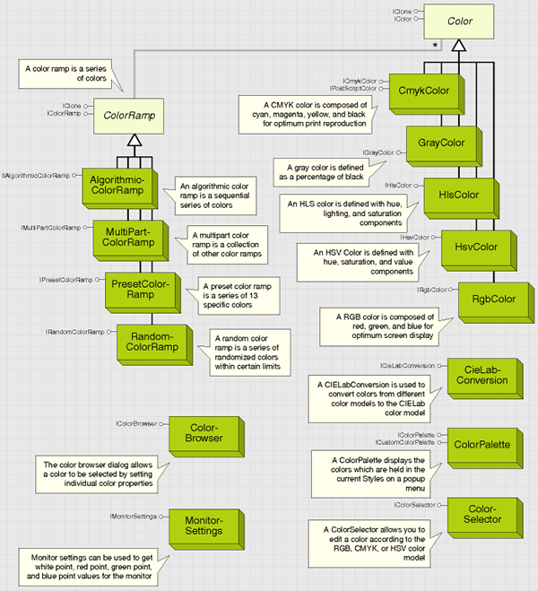
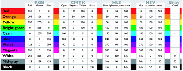
Color is used in many places in ArcGIS applications—in feature and graphics symbols, as properties set in renderers, as the background for ArcMap or ArcCatalog windows, and as properties of a raster image. The type of color model used in each of these circumstances will vary. For example, a window background can be defined as red, green, and blue (RGB) colors because display monitors are based on the RGB model. A map made ready for offset press publication can have cyan, magenta, yellow, and black (CMYK) colors to match printer's inks. See the following illustration of color objects:
RGB color model
Color can be represented using a number of different models, which often reflect the way colors can be created. You may be familiar with the RGB color model, which is based on the primary colors of light—red, green, and blue. When red, green, and blue rays of light coincide, white light is created. The RGB color model is therefore termed additive, as adding the components together creates light. By displaying pixels of red, green, and blue light, your computer monitor is able to portray hundreds, thousands, and millions of different colors. To define a color as an RGB value, give a separate value to the red, green, and blue components of the light. A value of 0 indicates no light and 255 indicates the maximum light intensity. See the following illustration:
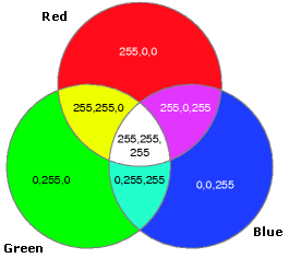
The following are rules for RGB values:
- If all RGB values are equal, the color is a gray tone.
- If all RGB values are 0, the color is black (an absence of light).
- If all RGB values are 255, the color is white.
CMYK color model
Another common way to represent color is the CMYK model, which is based on the creation of colors by spot printing. Cyan, magenta, yellow, and black inks are combined on paper to create new colors. The CMYK model, unlike RGB, is termed subtractive, as adding all the components together creates an absence of light (black). See the following illustration:
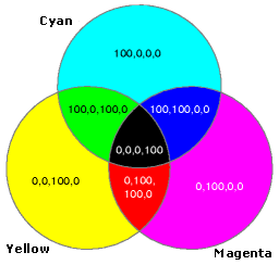
Cyan, magenta, and yellow are the primary colors of pigments—in theory you can create any color by mixing different amounts of cyan, magenta, and yellow. In practice, you also need black, which adds definition to darker colors and is better for creating precise black lines.
HSV color model
The hue, saturation, and value (HSV) color model describes colors based on a color wheel that arranges colors in a spectrum. The hue value indicates where the color lies on this color wheel and is given in degrees. For example, a color with a hue of 0 will be a shade of red, whereas a hue of 180 will indicate a shade of cyan. See the following illustration:
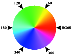
Saturation describes the purity of a color. Saturation ranges from 0 to 100; therefore, a saturation of 20 indicates a neutral shade, whereas a saturation of 100 indicates the strongest and brightest color possible. The value of a color determines its brightness, with a range of 0 to 100. A value of 0 always indicates black; however, a value of 100 does not indicate white, it indicates the brightest color possible. Hue is simple to understand, but saturation and value can be confusing. It helpd to remember the following rules:
- If value equals 0, the color is black.
- If saturation equals 0, the color is a shade of gray.
- If value equals 255 and saturation equals 0, the color is white.
HLS color model
The hue, lightness, and saturation (HLS) model has similarities with the HSV model. Hue is based on the spectrum color wheel with a value of 0 to 360. Saturation again indicates the purity of a color, from 0 to 100. However, instead of value, a lightness indicator is used with a range of 0 to 100. If lightness is 100, white is produced, and if lightness is 0, black is produced. The last color model is grayscale. 256 shades of pure gray are indicated by a single value. A grayscale value of 0 indicates black and a value of 255 indicates white. See the following illustration:

CIELAB color model
The Commission Internationale de l'Eclairage (CIELAB) color model is used internally by ArcObjects, as it is device independent. The model, based on a theory known as opponent process theory, describes color in terms of three opponent channels. The first channel, known as the 1 channel, traverses from black to white. The second, or 2 channel, traverses red to green hues. The last channel, or 3 channel, traverses hues from blue to yellow. See the following illustration:
Objects that support the IColor interface allow precise control over any color used in the ArcObjects model. You can get and set colors using a variety of standard color models—RGB, CMYK, HSV, HLS, and grayscale. See the following illustration:
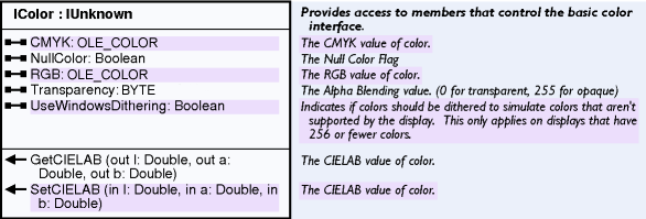
The properties on the IColor interface define the common functionality of all color objects. Representations of colors are held internally as CIELAB colors. The CIELAB color model is device independent, providing a frame of reference to allow faithful translation of colors between one color model and another.
You can use the getCIELAB and setCIELAB methods of the IColor interface to interact directly with a color object using the CIELAB model. Although colors are held internally as CIELAB colors, you don't need to deal directly with the CIELAB color model—you can use the IColor interface to read and define colors, or you can use the following code example, which essentially performs the same action but lets you see how the conversion is performed.
[Java]
public int getRGB(int red, int blue, int green){
    int RGB = red + (100 * green) + (10000 * blue);

    return RGB;
}
When reading the RGB property, set the useWindowsDithering property to true. If useWindowsDithering is false, the RGB property returns a number with a high byte of 2, indicating the use of a system color, and the RGB property returns a value outside of the expected range.
If you write to the RGB property, the useWindowsDithering property is set to true. For more information on converting individual byte values to long integer representation, look for topics on color models and hexadecimal numbering in your development environment's online Help system.
The IColor interface also provides access to colors through another color model—CMYK. The CMYK property can be used in a similar way as RGB to read or write a long integer representing the cyan, magenta, yellow, and black components of a particular color—the difference being that the CMYK color model requires four values to define a color. See the following code example:
[Java]
public int convertCMYKToInt(long black, long yellow, long magenta, long cyan){
    int value = black + (100 * yellow) + (10000 * magenta) + (1000000 * cyan);
    return value;

}
Setting the NullColor property to true results in the set color being nullified. All items with color set to null will not appear on the display. This only applies to the specific color objects—not all items with the same apparent color; therefore, you can have different null colors in one Map or PageLayout.
IColor also has two methods to convert colors to and from specific CIELAB colors, using the parameters of the CIELAB color model. You can set a color object to a specific CIELAB color by using SetCIELab or read CIELAB parameters from an existing color by using GetCIELab (see the CieLabConversion coclass).
Color transparency does not get used by the feature renderers; instead, a display filter is used. Setting the transparency on a color has no effect, unless the objects using the color honor this setting. The Color class is only an abstract class—when dealing with a color object, you always interact with one of the color coclasses. RGBColor, CMYKColor, GrayColor coclass, HSVColor, and HLSColor are all creatable classes, allowing new colors to be created programmatically according to the most appropriate color model.
Color ramps
The objects supporting the IColorRamp interface offer a simple way to define a series of colors for use elsewhere in ArcObjects. For example, you can set a color ramp directly onto the ColorRamp property of the IGradientFillSymbol interface of a FillSymbol, or you can create a color ramp to define the colors used in a ClassBreaksRenderer. The individual ColorRamp objects offer different ways of defining the criteria that determine which colors will comprise the ColorRamp.
Random colors can be created using the RandomColorRamp and sequential colors can be created using the AlgorithmicColorRamp. The PresetColorRamp coclass contains 13 colors, allowing the creation of ramps mimicking ArcView GIS 3.x color ramps. In addition, the MultiPartColorRamp allows you to create a single color ramp that concatenates other color ramps, providing unlimited color ramp capabilities. See the following illustration:

ColorRamps are used in the following ways in ArcObjects:
- Accessing the individual colors in a ramp
- Using the ramp object directly as a property or in a method of another object.
A color ramp can be set up and its individual colors accessed. For example, when a UniqueValueRenderer is created, each symbol in its symbol array should be set individually, using colors from a color ramp. To retrieve individual colors from a color ramp, set the size property according to the number of color objects you want to retrieve from the ramp. Call the CreateRamp method, which populates the color and the color properties. The color property holds a read-only, zero-based array of color objects returned by index.
The following code example shows the creation of a RandomColorRamp and the generation of 10 color objects from that ramp. The Boolean parameter used in the CreateRamp method is checked after the method is called to ensure the colors were generated correctly.
[Java]
RandomColorRamp colorRamp = new RandomColorRamp();
colorRamp.setSize(10);
boolean[] state = new boolean[1];
colorRamp.createRamp(state);
if (state[0]){
    for (int i = 0; i < colorRamp.getSize(); i++){
        //Access the color array and set the colors
        //for an array of synbols or map layers.
    }
}
The colors property returns an enumeration of colors and is useful as a lightweight object to pass between procedures. A color ramp object can be used directly—for example, the ColorRamp property of the IGradientFillSymbol can be set to a specific color ramp object. The MultiPartColorRamp also uses color ramp objects directly by passing the object as a parameter in the AddRamp method.
The following code example shows a GradientFillSymbol object being created with an AlgorithmicColorRamp as its fill. The IntervalCount is set, which decides the amount of colors in the gradient fill.
[Java]
AlgorithmicColorRamp algoRamp = new AlgorithmicColorRamp();
algoRamp.setFromColor(myFromColor);
algoRamp.setToColor(myToColor);
GradientFillSymbol symbol = new GradientFillSymbol();
symbol.setColorRamp(algoRamp);
symbol.setIntervalCount(5);
If the ramp is used directly, as shown in the preceding code example, it is not necessary to set the size property or to call the createRamp method. In these cases, the parent object uses the information contained in the color ramp object to generate the number of colors it requires. The size property will be ignored.The name property stores a string, which you may want to use to keep track of your color ramps—it is not used internally by ArcObjects.
Symbols
ArcObjects uses the following categories of symbols to draw geographic features:
- Marker symbols
- Line symbols
- Fill symbols
These same basic symbols are also used to draw graphic elements, such as neatlines and north arrows, on a map or PageLayout.
The TextSymbol is used to draw labels and other textual items. The 3DChartSymbol is used to draw charts. In the case of a graphic element, a symbol is set as a property of each element. Layers, however, are drawn with a renderer, which has one or more symbols associated with it. The size of a symbol is always specified in points (such as the width of a line), but the size of their geometry (such as the path of a line) is determined by the item they are used to draw.
Most items, when created, have a default symbol, so instead of creating a new symbol for every item, you can modify the existing one. Another way to get a symbol is to use a style file. ArcObjects uses style files, which are distributable databases, to store and access symbols and colors. Many standard styles, offering thousands of predefined symbols, are available during the installation process. Using the StyleGallery and StyleGalleryItem classes, you can retrieve and edit existing symbols, which may be more efficient than creating symbols from scratch.
This section describe how to create all the different symbols from first principles. The ISymbol interface provides high-level functionality for all symbols. It allows you to draw any symbol directly to a device context. A device context is an internal Windows structure—each window has a device context handle, or hDC. See the following illustration:

The setupDC, draw, and resetDC methods can be used in conjunction with the ROP2 property to draw a symbol to a device context, providing a familiar procedure for those who previously worked with device context drawing. Calling the setupDC method selects the symbol into the specified device context and setting the ROP2 property to one of the esriRaster-OpCodes specifies how the symbol is drawn.
Subsequently calling the Draw method draws the symbol, using the geometry parameter from the Draw method to the device context.
The following code example demonstrates drawing to a device context, where pDisplay is a valid display object, pPoint is a valid Point in display coordinates, and pSymbol is any valid symbol. The following are two important points to note:
- Call startDrawing on the display before using the Draw method, as this sets up the display's device context. Call finishDrawing on the display after you have finished.
- Call resetDC after you finish drawing with a symbol, which restores the device context to its original state.
screenDisplay.startDrawing(screenDisplay.getHDC(), (short)
    esriScreenCache.esriNoScreenCache);
symbol.setupDC(screenDisplay.getHDC(), screenDisplay.getDisplayTransformation());
symbol.draw(point);
symbol.resetDC();
screenDisplay.finishDrawing();
Symbol level drawing
You can use symbol level drawing to alter the draw order of features within feature layers. By using symbol level drawing, you can control the draw order of features on a symbol by symbol basis. This means that features do not necessarily need to be drawn in the same order that feature layers appear in the table of contents.
With symbol level drawing, you can control when a feature draws by controlling when the feature's symbol draws. Furthermore, when multilayer symbols are used, you can control the drawing order of individual symbol layers.
Using symbol level drawing is useful for maps with cased lines because it can be used to create overpass and underpass effects where the line features cross, which is a good way to show connectivity. Symbol level drawing can be used to achieve other advanced effects as well.
IMapLevel is the interface that you use to assign a map level (or levels if the symbol is multilayer) to a symbol, thus preparing it to be used with symbol level drawing. Not all symbols support this interface. If you assign a symbol with map levels to a graphic element, the levels will be ignored. ISymbol.draw also ignores levels. See the following illustration:

Using symbol level drawing
Do the following to use symbol level drawing:
- Turn on symbol level drawing for a layer using ISymbolLevels.useSymbolLevels, or for your entire map using IMap.setUseSymbolLevels.
- For each layer in your map that you want to use symbol levels, access the layer's renderer using IGeoFeatureLayer.getRenderer.
- Access your layer's symbols through the renderer.
- Using IMapLevel, set symbol levels on your layer's symbols. Symbols with MapLevel = 0 draw first, then symbols with MapLevel = 1, continuing until the highest MapLevel is reached. If two symbols have the same MapLevel, the features drawn with these symbols are drawn in the normal layer order. A MapLevel of –1 for a multilayer symbol (MultiLayerMarkerSymbol, MultiLayerLineSymbol, MultiLayerFillSymbol) indicates that each of the symbol's individual layers are drawn with their individual MapLevel.
Join and merge
Join and merge are graphical user interface (GUI) terms used to help users set up symbol levels. The following illustrations show the effect of joining a symbol, which makes features with the same symbol appear to connect to each other.
Merge makes features with different symbols appear to connect. Both of these effects are implemented behind the scenes using the symbol level objects and interfaces. You can toggle symbol level drawing on or off, using ISymbolLevels.setUseSymbolLevels for a layer, or for a .mxd file built in ArcGIS 8.3 or earlier, for your entire map using IMap.setUseSymbolLevels.
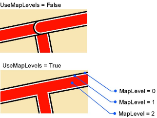
The following code example turns on symbol level drawing for the layer in the map and sets up the multi-layer symbol assigned to the layer to be joined:
[Java]
//...
if (map.getLayer(0)instanceof IGeoFeatureLayer){
    IGeoFeatureLayer layer = (IGeoFeatureLayer)map.getLayer(0);
    ISymbolLevels levels = (ISymbolLevels)layer;
    levels.setUseSymbolLevels(true);
    if (renderer.getSymbol()instanceof IMultiLayerLineSymbol){
        IMultiLayerLineSymbol multi = (IMultiLayerLineSymbol)renderer.getSymbol();
        setMapLevel((IMapLevel)multi,  - 1);
        for (int i = 0; i < multi.getLayerCount(); i++)
            setMapLevel((IMapLevel)multi.getLayer(i), multi.getLayerCount() - (i + 1)
                );
    }
}

//...


public void setMapLevel(IMapLevel level, int i){
    if (level != null){
        try{
            level.setMapLevel(i);
        }
        catch (Exception e){
            e.printStackTrace();
        }
    }
}
Marker symbols
The following illustration shows marker symbol objects:
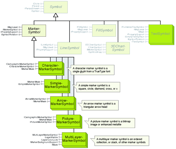
The IMarkerSymbol interface represents MarkerSymbol properties (angle, color, size XOffset, and YOffset). See the following illustration:

IMarkerSymbol is the primary interface for all marker symbols. All other marker symbol interfaces inherit the properties and methods of IMarkerSymbol. The interface has five read_write properties that allow you to get and set the basic properties of any MarkerSymbol. The Color property can be set to any IColor object and its effects are dependent on the type of coclass you are using. See the following illustration:

The Size property sets the overall height of the symbol if the symbol is a SimpleMarkerSymbol, CharacterMarkerSymbol, PictureMarkerSymbol, or MultiLayerMarkerSymbol. For an ArrowMarkerSymbol, setSize sets the length (the units are points). The default size is eight for all marker symbols except the PictureMarkerSymbol—its default size is 12.
The Angle property sets the angle in degrees to which the symbol is rotated counterclockwise from the horizontal axis (its default is 0). The XOffset and YOffset properties determine the distance to which the symbol is drawn offset from the actual location of the feature. The properties are in printer's points, have a default of zero, and can be negative or positive. Positive numbers indicate an offset above and to the right of the feature and negative numbers indicate an offset below and to the left.
The following code example shows how to create an ArrowMarkerSymbol and set only the properties inherited from IMarkerSymbol:
[Java]
ArrowMarkerSymbol arrow = new ArrowMarkerSymbol();
arrow.setAngle(60);
arrow.setSize(50);
arrow.setXOffset(20);
arrow.setYOffset(30);
arrow.setColor(myColor)
The size, XOffset, and YOffset of a marker symbol is in printer point of 1/72 of an inch.
The following illustration shows the types of marker symbols:
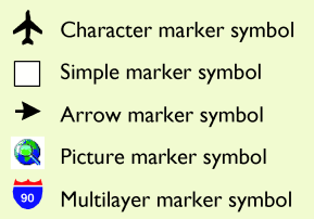
The rotation of a marker symbol is specified in mathematical notation. See the following illustration:
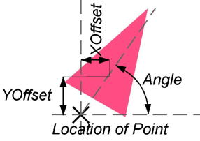
The following illustrations show each of the marker symbol types:
|
Simple marker symbols
|

|
|
Arrow marker symbols
|

|
|
Character marker symbols
|

|
|
Picture marker symbols
|

|
|
Multilayer marker symbols
|

|
Line symbols
The following illustration shows line symbol objects:
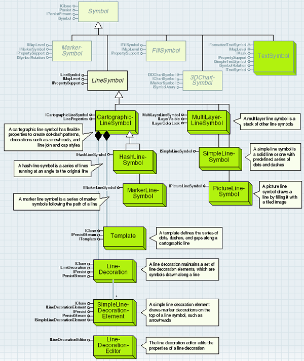
The ILineSymbol interface represents the color and width properties; all line symbols have these properties in common. See the following illustration:

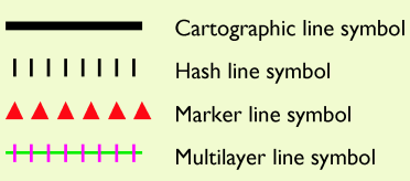
ILineSymbol is the primary interface for all line symbols; all line symbols inherit the properties and methods of ILineSymbol. The interface has two read_write properties that allow you to get and set the basic properties of any line symbol. The color property controls the color of the basic line (it does not affect any line decoration that is present—see the ILineProperties interface) and can be set to any IColor object. The color property is set to black by default except for the SimpleLineSymbol, which has a default of mid-gray. The width property sets the overall width of a line with points as units. For a HashLineSymbol, the width property sets the length of each hash—see HashLineSymbol for more information. The default width is 1 for all line symbols except MarkerLineSymbol, which has a default width of 8. See the following illustration:
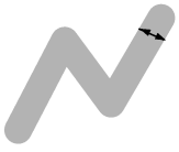
A line symbol represents how a one-dimensional feature or graphic is drawn. Straight lines, polylines, curves, and outlines can be drawn with a line symbol. The width of a line symbol is in printer points—about 1/72 of an inch. See the following illustration:
Fill symbols
The following illustration shows fill symbol objects:
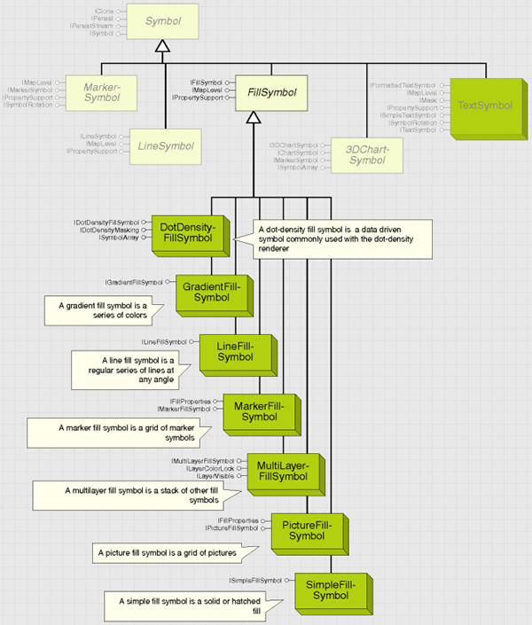
The IFillSymbol interface represents the color and outline properties; all fill symbols have these properties in common. See the following illustration:

The IFillSymbol interface, inherited by all the specialist fill symbols in ArcObjects, has two read_write properties. The color property controls the color of the basic fill and can be set to any IColor object. See the following illustration:

The outline property sets an ILineSymbol object, which is drawn as the outline of the fill symbol. By default, the outline is a solid SimpleLineSymbol, but you can use any type of line symbol as your outline. The outline is centered on the boundary of the feature; therefore, an outline with a width of 5 will overlap the fill symbol by a visible amount. See the following illustration:
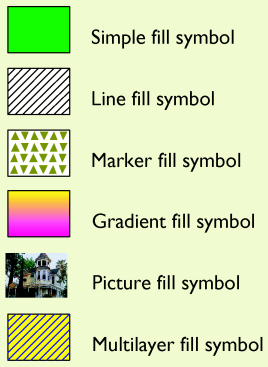
A fill symbol specifies how the area and outline of any polygon is to be drawn. See the following illustration:

Text symbols
The following illustration shows text symbol objects:
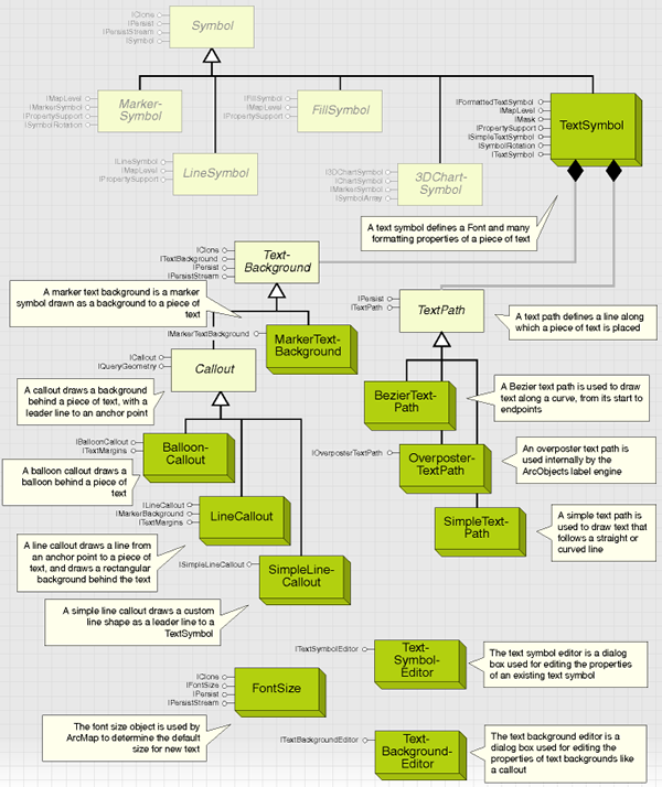
The TextSymbol coclass provides the object that is used to symbolize text in graphic elements, annotation, labels, and so on. A TextSymbol defines more than fonts. Its three main interfaces, ITextSymbol, ISimpleTextSymbol, and IFormattedTextSymbol, controls the text's appearance and how individual characters display. Extended ASCII characters are supported by the TextSymbol. See the following illustration:
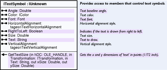
The ITextSymbol interface is the primary interface for defining text characteristics and is inherited by the ISimpleTextSymbol and IFormattedTextSymbol interfaces; may not need to be declared specifically. It contains the font property, which is the first logical step to defining a new TextSymbol. To set a font, create a Component Object Model (COM) font object. Using the IFontDisp interface of your font, set the name of the font. Set the IFontDisp to italic, bold, strikethrough, or underlined and set the CharacterSet and weight. See the following code example:
[Java]
StdFont font = new StdFont();
font.setName("ESRI Cartography");
font.setBold(true);
Set the font, color (as any coclass supporting IColor), and size (in points). The text property is used for a stand-alone TextSymbol object only (such as a TextSymbol in a style file); a TextElement draws text according to the text property of the TextElement coclass. Set the HorizontalAlignment and VerticalAlignment relative to the text anchor. See the following illustration:

Each font can include different character sets to allow for different alphabets and symbology. For most applications, you won't need to swap character sets from the default. The StdFont object is defined in the stdole2.tlb type library. Other development environments provide a similar implementation. If no generic font class is available, the esriSystemUI.SystemFont class can be used as it provides similar functionality as the stdole2.Font class.
If the TextSymbol is used to draw text to a point, not along a line (see TextPath), you can use the angle property to rotate the text string. The angle property specifies the angle of the text baseline, in degrees from the horizontal and defaults to zero. For Hebrew and Arabic fonts, set the RightToLeft property to true to lay the text string out in a right-to-left reading order.
For any existing TextSymbol, the size in x,y directions can be calculated using the GetTextSize method. Having set a size that defines the font height, the GetTextSize method calculates the height and length of the symbol in points. The GetTextSize method ignores the TextPath property if it is set through the ISimpleTextSymbol interface. GetTextSize is useful for calculating text placements on a PageLayout or whether a text string should be truncated to fit within a certain space.
The following code example shows the use of this method, where pDisplay is the IDisplay of the PageLayout or map that the TextSymbol belongs to and pTextSymbol is a valid TextSymbol.
The StartDrawing and FinishDrawing calls are necessary to make sure the hDC of the display is valid. The dblX and dblY variables are populated respectively with the height and length of the text parameter when drawn with the pTextSymbol symbol.
[Java]
double[] x = {
    0
};
double[] y = {
    0
};
screenDisplay.startDrawing(0, (short)esriScreenCache.esriNoScreenCache);
textSymbol.getTextSize(display.getHDC(), display.getDisplayTransformation(),
    "My Text", x, y);
screenDisplay.finishDrawing();
Chart symbols
3DChartSymbol is an abstraction of the three types of chart symbols. It represents a marker symbol, which can be used by a ChartRenderer to symbolize geographical data by multiple attributes. Although they are generally used by a ChartRenderer, if all the properties are set appropriately, you can also use the symbol as a MarkerSymbol to symbolize an individual feature or element. See the following illustration:

Use IChartSymbol to calculate the size of bars or pie slices in a chart symbol. The maximum attribute value that can be represented on the chart is used to scale the other attribute values in a chart. Always set this property when creating a 3DChartSymbol. When creating a ChartRenderer, you should have access to the statistics of your FeatureClass. Use these statistics to set the MaxValue property to the maximum value of the attribute or attributes being rendered, for example, if there are two fields rendered with a chart symbol, one containing attribute values from 0 to 5 and one containing attribute values from 0 to 10, set MaxValue to 10. See the following code example:
[Java]
BarChartSymbol symbol = new BarChartSymbol();
symbol.setMaxValue(10);
The Value property contains an array of values indicating the relative height of each bar or width of each pie slice. If using the ChartSymbol in a ChartRenderer, you do not need to set this property. The value array is populated repeatedly during the draw process by the ChartRenderer, using attribute values from the specified attribute fields from the FeatureClass coclass to create a slightly different symbol for each feature.
All values are set back to 0 after the draw has completed. If you want to use the symbol independently of a ChartRenderer, set the value array with the values you want to use in the bar or pie chart.
Display feedbacks
The following illustration shows display feedback objects:
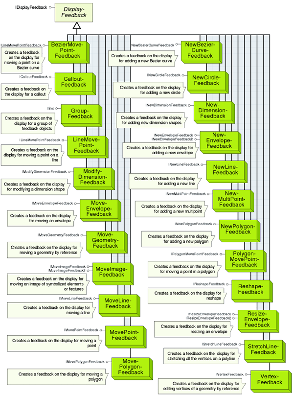
The set of objects that implement the IDisplayFeedback interface gives you fine-grained control over customizing the visual feedback when using the mouse to form shapes on the screen display. You can direct the precise visual feedback for tasks, such as adding, moving, or reshaping features or graphic elements. The objects can also be used without creating any features or elements for a task, such as measuring the distance between two points.
Typically, you would use the display feedback objects in code that handles the mouse events of a tool based on the ITool interface, such as onMouseDown and onMouseMove. The mouse events to program depend on the task, for example, when adding a new envelope, program the display feedback objects in the onMouseDown, mouseMove, and onMouseUp events. When digitizing a new polygon, program the onMouseDown, onMouseMove, and mouseDblClick events.
When you are collecting points with the mouse to pass to the display feedbacks, you can use the toMapPoint method on IDisplayTransformation to convert the current mouse location from device coordinates to map coordinates. Although the feedback objects (excluding the GroupFeedback object) all have common functionality, their behavior varies. These variations can be divided as follows:
- Feedbacks that return a new geometry—The interfaces for these objects have a Stop method that returns the new geometry. These objects are NewEnvelopeFeedback, NewBezierCurveFeedback, NewDimensionFeedback, NewLineFeedback, NewPolygonFeedback, MoveEnvelopeFeedback, MoveLineFeedback, MovePointFeedback, MovePolygonFeedback, BezierMovePointFeedback, LineMovePointFeedback, PolygonMovePointFeedback, ReshapeFeedback, ResizeEnvelopeFeedback, and StretchLineFeedback.
- Feedbacks for display purposes only—The developer is required to calculate the new geometry, for example, use the start and end mouse locations and calculate the delta x and delta y shifts, then update or create the geometry. These feedback objects are MoveGeometryFeedback, MoveImageFeedback, NewMultiPointFeedback, and VertexFeedback.
The objects are used in applications to allow graphic elements to be digitized and modified in the map (data view) and layout (layout view) and are also used by the ArcObjects feature editing tools. Some of the feedback objects have a constraint property that determines the feedback's behavior. These constraints can specify, for example, that a ResizeEnvelopeFeedback maintains the aspect ratio of the input envelope.
The details of these constraints are given with individual feedbacks. The display feedback objects also provide some of the base functionality for the rubberband objects. You should use the rubberband objects first if they suit your requirements; select the display feedback objects if you want greater control over the user interface when modifying graphics or features. This greater control comes at the cost of more code. See the following illustration:

The IDisplayFeedback interface is used to define the common operations on all of the display feedback operations. These include moving, symbolizing, and refreshing the display feedbacks as well as setting a display feedback object's display property (for example, setting it to IActiveView.getScreenDisplay).
The IDisplayFeedback interface is useful only in combination with one of the display feedback objects and its derived interfaces, for example, the NewPolygonFeedback object and its INewPolygonFeedback interface. Nearly all of the display feedback interfaces employ interface inheritance from IDisplayFeedback; hence, there is no need to use QueryInterface to access its methods and properties.
Typically, the display and symbol properties are set when a display feedback object is initialized, while the MoveTo method is called in a mouse move event. Setting the symbol property is optional. If it is not set, a default symbol is used.
The refresh method is used to redraw the feedback after the window has been refreshed (for example, when it is activated again), and it should be called in response to the tool's refresh event. The hDC parameter, required by the refresh method, is passed into the subroutine.
In the following code example, a check is made to verify polyFeedback—a member variable NewPolygonFeedback object—has been instantiated (if the user is currently using the feedback). If it has been instantiated, the refresh method is called.
[Java]
public void refresh(int hDC){
    If(polygonFeedback != null)polyFeedback.refresh(hDC)
}
The following code example shows how to use the IDisplayFeedback interface with the INewEnvelopeFeedback interface to create a display feedback that allows the user to add a new polygon. This code example shows the visual feedback; further code is required if you want to add that drawn shape as a map element or feature. The new envelope feedback object is declared as a member variable.
[Java]
INewEnvelopeFeedback newEnvFeed;
Other objects are locally declared—env as IEnvelope, screenDisplay as IScreenDisplay, lineSym as ISimpleLineSymbol, and startPoint and movePoint as IPoint. The following code example is placed in the onMouseDown event to set up the display and symbol properties and to call INewEnvelopeFeedback.start with the current mouse location in map units.
[Java]
NewEnvelopeFeedback newEnvFeed = new NewEnvelopeFeedback();
newEnvFeed.setDisplayByRef(screenDisplay);
newEnvFeed.setSymbolByRef(ineSym);
newEnvFeed.start(startPoint);
The following code example is placed in the onMouseMove event to move the display feedback to the current mouse location in map units, using the moveTo method from IDisplayFeedback:
[Java]
newEnvFeed.moveTo(movePoint);
The following code example is placed in the onMouseUp event to return the result using the stop method from INewEnvelopeFeedback:
[Java]
env = newEnvFeed.stop();
Rubber bands
The following illustration shows rubber band objects:
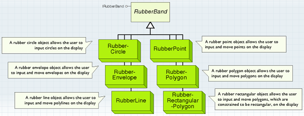
The RubberPoint, RubberEnvelope, RubberLine, RubberPolygon, RubberRectangularPolygon, and RubberCircle coclasses, all implementing the IRubberBand interface, allow the user to digitize geometries on the display using the mouse—to create geometry objects or to update existing ones. As such, they can be viewed as simple versions of the feedback objects.
Some examples of uses for these rubber band objects include dragging an envelope, forming a new polyline, or moving a point. Each rubber class support the IRubberBand interface, but the behavior depends on the class used. See the following screen shot:

The IRubberband interface has the trackExisting and trackNew methods, which are used to move existing geometries and create new geometries, respectively. These methods are called from the code for a tool's onMouseDown event and handle all subsequent mouse events. The methods capture subsequent mouse and keyboard events, such as onMouseMove, onMouseUp, and KeyDown events and complete when they receive an onMouseUp event or abort if you press the Esc key.
The events are trapped by the rubberband objects, which means a small amount of code is required to use them, although this comes at the expense of flexibility. Typically, these objects are used for simple tasks, such as dragging a rectangle or creating a new line. Operations that involve moving the vertices of existing geometries require the feedback objects to be used instead.
The trackNew method has an IScreenDisplay object representing the ScreenDisplay to draw the rubberband and an ISymbol object to use for drawing the rubberband. If no symbol is given, the default symbol is used. The method returns a new geometry object—the type of geometry returned depends on the class used.
The RubberPolygon class returns a polygon object. If the method fails to complete (that is, if the user presses the Esc key), nothing is returned. The following are the types of geometry that are returned for TrackNew by each of the rubber objects:
- RubberCircle—ICircularArc
- RubberEnvelope—IEnvelope
- RubberLine—IPolyline
- RubberPoint—IPoint
- RubberPolygon—IPolygon
RubberRectangularPolygon—IPolygon
The following code example shows how to use the trackNew method of IRubberBand with a RubberLine object.
[Java]
public void onMouseDown(int button, int shift, int x, int y){
    super.onMouseDown(button, shift, x, y);
    try{
        IMap map = hookHelper.getFocusMap();
        //Create new RubberLine.
        RubberLine rubberLine = new RubberLine();
        //Track a new polyline on current document's display using default symbol.
        IGeometry geom = rubberLine.trackNew(hookHelper.getActiveView()
            .getScreenDisplay(), null);
    }
    catch (Exception e){
        e.printStackTrace();
    }
}
Trackers
The following illustration shows tracker objects:
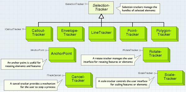
The following are the types of selection trackers:
- Envelope tracker—Allows the user to move and resize the element. This functionality is implemented by the EnvelopeTracker object for all element types, including point, line, polygon, and group elements.
- Vertex edit tracker—Allows the user to move vertices of lines, polygons, curves, and curved text. This functionality is implemented by the LineTracker and PolygonTracker objects.
- Callout tracker—Allows the user to move a text callout. This functionality is implemented by the CalloutTracker objects.
The PointTracker object is not currently used. Moving and resizing of point elements is handled by envelope trackers, the size of the envelope corresponding to the symbolized point. Although the selection trackers are coclasses, only cocreate one if you are building a custom element when implementing IElement.selectionTracker.
The envelope tracker operates on all element types. See the following illustration:

The line and polygon tracker lets you manipulate the vertices of polylines and polygons. See the following illustration:

The callout tracker lets you manipulate text callouts. See the following illustration:

The ISelectionTracker interface controls the selection handle user interface. You can use ISelectionTracker to provide different behavior, for example, the Element Movement tool that snaps elements to a grid. However, it is more likely that you will use this interface when building a custom object, such as an element. You can gain access to selection trackers with IElement.getSelectionTracker, IElementEditVertices.getMoveVerticesSelectionTracker, or IGraphicsContainerSelect.getSelectionTracker. See the following illustration:
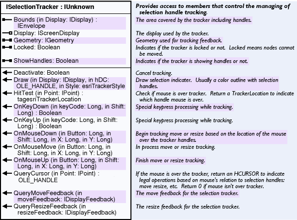
When using IElement, you will get an envelope tracker or edit vertices tracker, depending on the state of the element. The following code example ensures that an envelope tracker is returned—if the element has a vertex edit tracker, it is changed to an envelope tracker and the document is refreshed.
[Java]
public void ensureEnvelopeTracker(IActiveView activeView, IElement element){
    try{
        IScreenDisplay display = activeView.getScreenDisplay();
        if (element instanceof IElementEditVertices){
            IElementEditVertices editVertices = (IElementEditVertices)element;
            if (editVertices.isMovingVertices()){
                editVertices.setMovingVertices(false);
                activeView.partialRefresh(esriViewDrawPhase.esriViewGeography, null,
                    element.getSelectionTracker().getBounds(display));
            }
        }
    }
    catch (Exception e){
        e.printStackTrace();
    }
}
After obtaining a reference to a selection tracker, always set the display property before using it. The geometry property of a selection tracker applies to the tracker, not the element—for envelope trackers, the geometry is a polygon created from the envelope shape; for vertex edit trackers, the geometry is a polygon or polyline as appropriate.
The geometry property is updated when the user finishes reshaping the element with the selection tracker. The hitTest method provides information about the position of the mouse. The returned values are defined by esriTrackerLocation: The enumeration names are relevant to envelope trackers, but hitTest can also be used with vertex edit trackers and callout trackers. In these cases, the returned values are LocationNone, LocationInterior, and LocationTopLeft. Many of the ISelectionTracker methods—for example, onMouseDown—correspond to user interface events. When controlling a selection tracker with a user interface tool, pass on the tool events to the selection tracker.
QueryMoveFeedback and QueryResizeFeedback return the feedback objects that the selection tracker is using. Draw is called by ArcObjects if the element is selected; normally you do not need to use this method (though it is important if you implement your own custom selection tracker).
The CancelTracker object is favored by many users. If the process used the CancelTracker object, you can press the Esc key and stop the process befor it is completed. The CancelTracker object is the object used by ArcObjects to monitor the Esc key (optionally, the space bar and mouse click also) and terminate processes at the request of the user. A CancelTracker is typically handed into or created just prior to functions that execute a lengthy operation. Before this operation begins, ITrackCancel.reset must be called; reset sets the state of the CancelTracker to uncancel and returns the internal counter, which is used to update progression to zero.
Within the innermost loop of the operation, call ITrackCancel.continue to check if the user canceled the operation. By default, a cancellation occurs under the following circumstances:
- The Esc key is pressed.
- The space bar is pressed (disable with CancelOnKeyPress property).
- The left mouse button is clicked (disable with CancelOnClick property).
- The right mouse button is clicked (disable with CancelOnClick property).
If any of these actions occurs, the ITrackCancel.continue method returns false and the operation's logic uses this indicator to exit the loop. Any object that exposes IProgressor or IStepProgressor, such as the ProgressDialog object, can be bound to the CancelTracker so that it updates correctly and efficiently with no additional code in the operation.
Once the progressor is connected to the CancelTracker via the progressor property, it updates automatically as the operation is executed. If the progressor is a step progressor, set the MaxRange to equal the number of iterations that the operation progresses through; match this number to the number of times Continue is called in the operation's innermost loop. For COM and various other parts of Windows to work correctly and responsively, Windows messages must be processed at regular intervals. For this reason, the CancelTracker's implementation processes non-input (mouse, keyboard) related messages every second during the operation if any messages are pending. This default frequency can be changed utilizing the ITrackCancel.checkTime property. As a developer, you can use the CancelTracker several ways. Some ArcObjects commands (such as IActiveView.output) take a CancelTracker object as an input parameter. See the following code example:
[Java]
CancelTracker cancel = new CancelTracker();
activeView.output < OLE_handle > ,  < screen resolution > ,  < pixel bounds > ,  <
    visible bounds > , pCancel
In this case, provide cancel capabilities by creating a CancelTracker object and passing it in the output method. The output method takes care of monitoring the Esc button and canceling the process if the user chooses to.
Another way to use a CancelTracker object is similar to the preceding process, but you are responsible for monitoring the object. Use this approach when the execution of your code takes a considerable amount of time and you want to give the user the option of canceling the process.
The following code example shows this process. The code is designed to loop through a set of selected network features and run the Connect method on them to ensure they are connected to the network. The CancelTracker object is included for aborting the process if the user accidentally selects too many features or wants the process to stop.
[Java]
public void testCancel(IEnumFeature enumFeats, CancelTracker cancel){
    try{
        IFeature feature = enumFeats.next();
        while (feature != null){
            if (feature instanceof INetworkFeature)
                ((INetworkFeature)feature).connect();
            if (!cancel.esri_continue()){
                JOptionPane.showConfirmDialog(null, "Process has been cancelled!");
            }
            feature = enumFeats.next();
        }
    }
    catch (Exception e){
        e.printStackTrace();
    }
}