
In this topic
Logo marker symbol example
Object Model Diagram: Click here
Description: This example provides a custom symbol, which draws a company logo to symbolize a point. Simple custom functionality is provided to alter the colors of the different parts of the symbol, and a property page is also provided to allow end users to edit the properties of the symbol.
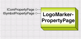
Design: Coclass LogoMarkerSymbol is a subtype of the MarkerSymbol abstract class. LogoMarkerPropertyPage is an accompanying property page coclass.
Categories: Marker Symbols, ESRI Property Pages, and Symbol Property Pages
Interfaces: IClone, ISymbol, IPersist, IMarkerMask, IMapLevel, IMarkerSymbol, ISymbolRotation, IDisplayName, IPropertySupport, IComPropertyPage, IPropertyPageContext, ISymbolPropertyPage
How to use
-
Open and build the project LogoMarkerSymbolVC.dsp to register the DLL and register to component categories.
-
Open ArcMap and add a layer with point features or a marker graphic element. Open the Symbol Selector for the item.
For a layer, right-click the layer in the ArcMap table of contents, click Properties, then in the Layer Properties dialog box, click the Symbology tab. The Single Symbol renderer should be selected by default; click the Symbol button to show the Symbol Selector.
For a marker element, right-click the element and click Properties. In the Properties dialog box, make sure the Symbol tab is selected, and click the Change Symbol button. -
In the Symbol Selector dialog box, click the Properties button to display the Symbol Editor.
-
In the Symbol Editor dialog box, pull down the Type list box and click Logo Marker Symbol.
You can now set the properties of a LogoMarkerSymbol. Click OK to select the symbol and return to the Symbol Selector.
Case for a custom Marker symbol
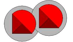
Imagine that the fictitious company logo shown here must be used to symbolize point features or graphic elements. You must be able to use it repeatedly, as part of a renderer or graphic, and at a wide variety of scales including large format output. You must also add the ability to alter the color of each section of the logo to indicate different divisions of the company.

To create a symbol like this by using the core ArcObjects symbol classes, you have a couple of options available.
You could create a PictureMarkerSymbol, as this may be used effectively to portray any design. However, changing the colors of the logo sections would require a different bitmap for each possible color combination. Also, PictureMarkerSymbols may appear pixelated when zoomed in; using a high resolution bitmap may solve this problem, but can also increase memory requirements, and slow down draw speeds.
Alternatively, you could construct a MultiLayerMarkerSymbol, with separate CharacterMarkerSymbols to represent the different parts of the logo. As the symbol is drawn with vectors, there would be no resolution problems. However, you would need to create a specialist TrueType font with glyphs designed to represent the different sections of the logo.
As no core symbol coclass provides the functionality you require, you can create a custom marker symbol.
This example provides a custom symbol that draws a company logo. Different colors can be used for the sections of the symbol.
Creating a subtype of MarkerSymbol
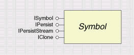
If you decide to create a custom symbol, start by reviewing the Display object diagram. You will see that all Symbol classes - markers, lines, fills, text, and charts - inherit from a common abstract class called Symbol.
Therefore, any type of custom symbol you create must begin by implementing the ISymbol interface, along with interfaces for cloning and persistence.
Any class that implements ISymbol can be drawn to a device; however, classes specialize in the type of objects they can draw.
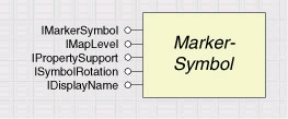
Looking again at the Display object model diagram, you can see that each coclass for drawing point features also inherits from the MarkerSymbol abstract class.
Therefore, to create a MarkerSymbol, you should also implement IMarkerSymbol, ISymbolRotation, IMapLevel, and IPropertySupport.
Looking at the existing MarkerSymbol classes, you can see many of them also implement IMarkerMask. This interface provides the ability to draw a standard mask around a MarkerSymbol, which can be useful when placing multicolored symbols on a multicolored background, as it helps the eye to identify the boundaries of the symbol more clearly. This interface is, therefore, also an appropriate interface to implement in this case.

A marker mask can help to distinguish symbols from a similarly colored background.
All MarkerSymbols also implement IDisplayName, which provides a string description of each type of symbol and which is used in the Symbol Properties Editor dialog box.
Creating the LogoMarkerSymbol
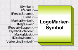
To solve the requirements of this example, you will create a subtype of MarkerSymbol, called LogoMarkerSymbol, registered to the Marker Symbols component category.
You will implement ISymbol, IMarkerSymbol, ISymbolRotation, IMapLevel, IMarkerMask, and IDisplayName, as well as the standard interfaces for cloning and persistence. To add the custom functionality, you will also create and implement a custom interface, ILogoMarkerSymbol.
Techniques for drawing
There are a number of ways you could perform the actual drawing of a symbol.
You can use the GeometryDraw class or the ISymbol::Draw or IDisplay::Draw methods. In this case, the shape of the logo would be stored as existing geometries (Polygons, Polylines, Envelopes, and so forth). You will be limited to drawing with existing geometries and symbols, but this approach does allow you to utilize the full functionality of ArcObjects to transform and adapt the shape and appearance of your symbol as required. This design may suit the production of a scale-dependent symbol, for example, that renders differently according to the current display scale.
You may decide to perform drawing operations using third party drawing libraries, or the low-level libraries available as part of the Windows platform. You may want to investigate the OpenGL standard or the Windows-specific DirectX libraries. Note that both were originally designed for use by C++ programmers and may not be a straightforward programming task in non-C++ environments.
In this example, you will use the Windows Graphics Device Interface (GDI) functions to draw the symbol.
Using GDI calls can produce efficient draw routines and also offers flexibility in the kind of drawing you can do. However, you need to be familiar with using GDI calls. Also, you may need to perform extensive mathematical calculations to transform your symbol's coordinates according to Size, Angle, and so on. As Windows GDI functions require instructions in device coordinates, you will store the shape of the logo in device coordinates.
Implementing ISymbol
The ISymbol interface is responsible for actually drawing a geometry to the appropriate device context, using the correct appearance, shape, size, and location.
When a refresh event is called, ArcMap will work out which shapes need to be drawn and in which order. It then uses the ISymbol interface to request that the shape draw itself.
Before any ISymbol is drawn, its SetupDC method is called, which receives information about the drawing device. Then the Draw method is called, which receives the shape and location (the Geometry) of the item to be drawn. Finally, the ResetDC method is called.
A general overview of the actions that should be performed by a custom symbol during each of these members is given below. This can be used as a guide for any symbol drawn using GDI functions.
If you make use of GDI calls to draw your symbol, you should use the SetupDC and ResetDC members of ISymbol to handle the adding and release of GDI objects, device contexts, and handles.
The actions performed in each of the draw methods are summarized here.
You will use the CreatePen and CreateSolidBrush GDI functions to define the appearance of a LogoMarkerSymbol, and the Chord and Polygon functions to draw the sections of the symbol to the device context. You will also need to use the SelectObject and DeleteObject GDI functions to maintain the device context objects correctly.
Add these declarations to your project. Also, declare a user-defined type called POINTAPI, as GDI functions require coordinates to be defined as POINTAPI structures.
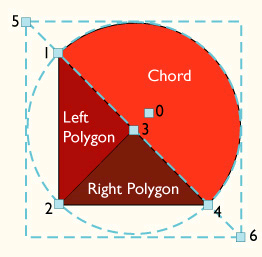
Now define an array of POINTAPI structures as a member variable of the LogoMarkerSymbol class. This array will hold the control points, which are the significant points you will use to define the shape and location of the logo in device coordinates.
The control points used by the drawing methods are stored in the m_pCoords array. They define the locations used for the Chord and Polygon GDI calls.
Now you can begin coding the ISymbol methods.
SetupDC method
In SetupDC you need to prepare the class members to draw to the specific device, which is passed in as parameters to this method (hDC and displayTransformation).
- First, store the passed-in information.
- Next, set up the device ratio. See the Null transformations and resolution in the Draw and QueryBoundary section later for more information.
- Calculate the size of the symbol in device coordinates. You will use these later in Draw.
- Now you are ready to create the pens and brushes, which you will use to fill and outline the sections of the symbol, and set up the ROP2 code used for the drawing. Save the existing values for all the GDI objects you will change, so you can replace these in ResetDC.
Draw method
In the Draw method, work out the location of each control point for the symbol, and draw the symbol based on these locations.
- First, check that the passed in Geometry parameter contains a valid object, then cast it to a Point.
- Transform the Point to device coordinates, using the device context and DisplayTransformation you saved in SetupDC. Call the CalcCoords function. This function will calculate the location of each of the control points used by the GDI functions (see the diagram on previous page).
- Then draw the separate sections of the symbol to the device.
ResetDC method
Complete the drawing functions by selecting back the old GDI pen and ROP code and releasing other GDI resources in the ResetDC method.
If using the Windows GDI to draw to the display, make sure you reselect the old GDI objects after drawing.
QueryBoundary method
In the QueryBoundary method you must populate the passed-in Boundary parameter, which is a Polygon, with the shape of your symbol in map coordinates.
The nonsymmetrical nature of the logo means that it is simpler to calculate the exact shape of the symbol, rather than approximating a shape. You can create the shape of the logo by working out the radius of the circular section of the logo (dRad) and the length of the triangular sections of the symbol (dVal).
QueryBoundary is a client-side storage function; therefore, you should add Point objects to the ISegmentCollection interface of the passed-in Boundary object.
ROP2 property
The ROP2 property indicates which type of pen (or Raster OPeration) is used to draw a symbol. The ROP2 code of the device can easily be changed using the GDI functions SetROP2 and GetROP2, but remember to change the ROP2 code back to its original value in ResetDC, as other symbols will be 'sharing' the same device.
The esriRasterOpCodes enumeration defines the possible ROP2 codes. Changing the ROP2 code can dramatically alter the appearance of the symbol.
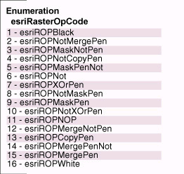
For more information on drawing with different raster operations, search Windows documentation. Windows raster operation constants correspond to esriRasterOpCodes.
Null transformations and resolution in Draw and QueryBoundary
(converting from map to device units)
As the scalar properties Size, XOffset and YOffset hold values in Points, you must convert from Points to device units (pixels) before drawing the symbol (for example, during SetupDC), using device coordinates.
You can calculate a device resolution, m_dDeviceRatio, in pixels per Point, using the DisplayTransformation passed to the SetupDC method.
SetupDeviceRatio calculates how many pixels on the device equal one printer's Point - this is used to transform Size, XOffset, and YOffset from Points to device units. Note that the ReferenceScale of the Transformation, if present, is also accounted for here.
In some situations your symbol may be required to draw to a device context for which this parameter is null - for example, when drawing to the table of contents. In this case, you can get the resolution directly from the screen by using the GetDeviceCaps Windows API call.
Once the device ratio is calculated, Draw can use the FromMapPoint function (see accompanying sample code) to convert the Geometry the symbol is drawn at from map units into device units.
The SetupDeviceRatio and FromMapPoint function together to transform map units to Points.
Converting from Points to map units
In the QueryBoundary method, you need to convert Size, XOffset, and YOffset from Points to map units to construct a Geometry in map units representing the boundary of your Symbol.
Add a function called PointsToMap to complete this conversion; if no DisplayTransformation is present, use the value from SetupDeviceRatio.
The PointsToMap function transforms values from Points to map coordinates.
Drawing efficiently
Code the ISymbol methods efficiently, as they may be called frequently. There are a number of issues you could consider to increase your symbol's drawing efficiency.
A symbol's draw methods may be called frequently; consider the efficiency of your code.
- Calculating and storing the shape of the Symbol
The LogoMarkerSymbol calculates the shape and size of the Symbol in two different coordinate spaces: in device units for ISymbol::Draw and in map coordinates for ISymbol::QueryBoundary and IMarkerMask::QueryMarkerMask.
Think about the amount of processing each set of calculations will require and which will limit the speed of these functions. Storing and calculating the shape of the symbol in both map and device coordinates may enable you to create a more efficient symbol; however, using a single method may make your code simpler and more maintainable.
Think also about the routines you use to manipulate the shape of your symbol; these may be called frequently. Therefore, providing a direct mathematical approach may be quicker than the QI's and object creation you may need to use to convert using the geometrical transformations inside ArcObjects.
- Caching the shape of the Symbol
If more than one item is drawn with exactly the same Symbol, the drawing sequence starts with a call to SetupDC. Then Draw is called once for each item, and finally, ResetDC is called. The diagram below shows the sequence of calls for a SimpleRenderer and a ClassBreaksRenderer.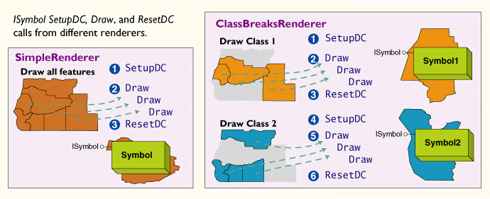
It may be most efficient to work out the size and shape of your Symbol once in the SetupDC method, then use this repeatedly in the Draw method by just changing its location, depending on how you draw your Symbol.
- Efficient object creation
Think about how your code will scale when it is used for hundreds of features or elements. For example, QueryBoundary is called frequently by ArcMap when drawing a FeatureLayer and when drawing elements. QueryBoundary is also called when displaying the TOC, saving the document, and displaying property pages that show the Symbol. You should ensure your QueryBoundary routine is efficient enough not to impede these processes, which may interrupt the user's work flow.
You could see a decrease in your draw times if you instantiate all the objects you need when the Symbol is instantiated, then reset the values each time.
For example, the QueryBoundsFromGeom function creates new Point objects to build the boundary of the Symbol.
You could declare Point objects as member variables m_pt1, m_pt2, and m_pt3, instantiate them when the class is initialized, and reuse them in the QueryBoundsFromGeom method.
This code can execute approximately 50 percent faster when you repeatedly call QueryGeometry.
Creating and implementing the ILogoMarkerSymbol interface
You need to provide a way to change the colors of the separate sections of the logo design.
Create an interface called ILogoMarkerSymbol, with four read-write properties, ColorLeft, ColorRight, ColorTop, and ColorBorder. For more information on how you can create a new interface, see the Developing Objects section.
The custom ILogoMarkerSymbol interface allows a client to change the colors of the different sections of the logo.
Implement ILogoMarkerSymbol in the LogoMarkerSymbol coclass. In each property, clone the incoming IColor parameters and set the appropriate member variable.
Implementing IMarkerSymbol
Implementing IMarkerSymbol allows ArcGIS to recognize that your class can be used to symbolize points. MarkerSymbol properties for the LogoMarkerSymbol. This interface is commonly used by the ArcGIS applications, for example, when setting Color and Size using the Element Properties dialog box.
Implementing IMarkerSymbol ensures that a Symbol is able to interact with the ArcMap user interface, for example the Element Properties dialog box
Code the Color property to refer to the predominant color at the top of the logo, by calling the ILogoMarkerSymbol::ColorTop property.
In the Angle property you can add a check for angles greater than 360 degrees.
Implementing ISymbolRotation
If you want your symbol to be able to adjust itself to a rotated map display, implement ISymbolRotation. Although it is not essential to implement this interface, it requires little extra coding, as you should have already added Symbol rotation code to allow for the IMarkerSymbol::Angle property.
When you rotate the symbol for drawing, simply subtract the Map rotation angle from the IMarkerSymbol::Angle. You can get the Map rotation value from the DisplayTransformation passed in SetupDC:
RotateWithTransform is True by default for existing ArcGIS symbols.
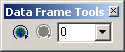
ISymbolRotation allows a Symbol to work with the Data Frame tools in ArcMap, rotating with the Map.
Implementing IMapLevel
IMapLevel is commonly used by the ArcMap Advanced Drawing Options to draw joined and merged symbols, most commonly those used to draw cased roads. It is simple to implement, as you only need to store a Long value in the read-write MapLevel property
This value will be used when your symbol is used in a MultiLayerMarkerSymbol, when the Advanced Drawing Options indicate symbols must be drawn joined and merged.
IMapLevel allows a symbol to take part in the ArcMap Advanced Drawing Options.
Implementing IMarkerMask
IMarkerMask is used to draw a mask around a symbol. The QueryMarkerMask method should populate the Boundary parameter with the shape of the symbol if drawn at the specified Geometry. The shape needs to be in map units, as it will be passed to the ISymbol::Draw method of an IFillSymbol by ArcMap.
By implementing IMarkerMask, you allow the framework to draw a mask area around your symbol.
First ensure the Boundary is empty, then use the same technique you used in ISymbol::QueryBoundary to populate Boundary.
Unlike QueryBoundary, however, QueryMarkerMask requires a Simple geometry, so simplify the geometry before returning.
Implementing IPropertySupport
IPropertySupport can be implemented in VC++ and is used to apply an object to one or more of the symbol's properties. It is a generic interface, which can be used by a client without the client needing to know the exact nature of the underlying class.
IPropertySupport is an optional interface.
In the Applies method, you should assess the incoming object reference pUnk, to see if it can be applied to a property of your class.
[VCPP] STDMETHODIMP CLogoMarkerSymbol::Applies(LPUNKNOWN pUnk, VARINT_BOOL *Applies)
{
if (!Applies)
return E_POINTER;
*Applies=VARIANT_FALSE;
IColorPtr ipColor(pUnk);
ILogoMarkerSymbolPtr ipLogo(pUnk);
if (ipColor != NULL && ipLogo != NULL)
*Applies=VARIANT_TRUE;
return S_OK;
}
In the CanApply method, check if the object can be applied at the particular moment the method is called; a more complex class may involve checking the internal state of the class). In the case of the LogoMarkerSymbol, the result does not depend on any state, so you can delegate the call to Applies.
In the Current property, check the incoming object reference - if it can be applied to any of the properties of the class, set the pUnk pointer to the current value of that property.
[VCPP] STDMETHODIMP CLogoMarkerSymbol::get_Current(LPUNKNOWN pUnk, LPUNKNOWN
*currentObject)
{
IColorPtr ipColor(pUnk);
if (ipColor)
{
IColorPtr ipCurrentColor;
get_Color(&ipCurrentColor);
ipCurrentColor.QueryInterface(IID_IUnknown, (void **)currentObject);
return S_OK;
}
...
}
In the Apply method, set the incoming object as the appropriate member of your symbol class. Note in the code below that the incoming object may be an instance of the LogoMarkerSymbol class itself, in which case the values of the incoming object are assigned to the class member by using the IClone::Assign method.
[VCPP] STDMETHODIMP CLogoMarkerSymbol::Apply(LPUNKNOWN NewObject, LPUNKNOWN *oldObject)
{
IColorPtr ipColor(NewObject);
if (ipColor)
{
get_Current(NewObject, oldObject);
put_Color(ipColor);
return S_OK;
}
ILogoMarkerSymbolPtr ipSymbol(NewObject);
if (ipSymbol)
{
get_Current(NewObject, oldObject);
IClonePtr ipClone(NewObject);
Assign(ipClone);
return S_OK;
}
return E_FAIL;
}
To be consistent with core symbols, you should at least apply an IColor object to the IMarkerSymbol::Color property, although you can extend this to allow the setting of any of your properties.
Initializing members
Add a private routine to the LogoMarkerSymbol class to initialize the member variables. Call this function from the class initialize.
Placing the initialization code in a separate function enables you to reset the LogoMarkerSymbol to default values at any point, which is particularly useful when implementing persistence.
Implementing cloning and persistence
Implementing cloning and persistence
Cloning and persistence are essential functions for any symbol. Every time a reference to a symbol is passed to a property page, the symbol object is cloned. This allows any changes made to the symbol to be discarded and also allows the change to be added to the Undo/Redo stack in ArcMap. Every time a map document is saved, all the symbols applied to features and graphic elements are persisted. Add a standard implementation of persistence and cloning for the LogoMarkerSymbol example. See the section Developing Objects, for more information on cloning and persistence.
In the IPersistVariant::Save method, save the persistence version number first, then each required member of the class.
In IPersistVariant::Load check the persistence version number first. Call the InitializeMembers function to set default values into the symbol, before reading values from the Stream, in the same order they were saved to set the member variables.
In the IClone::IsEqual method, you may decide that the source and other symbols are equal if the RGB property values of IColor members are equivalent, instead of QIing to IClone on the color class and checking its IsEqual member in turn.
Symbol Property Pages
All core symbols have a property page that is displayed in the Symbol Editor dialog box. This allows the user to edit the properties of the symbol in the user interface. Some more complex symbols have multiple property pages, displayed as separate tabs in the dialog box.
It is not absolutely essential for a custom Symbol coclass to have an accompanying property page, although it is recommended that you do. If you only intend a Symbol to be applied and edited programmatically, you need not implement a property page, but users may be confused when they try to change the properties of the Symbol in the editor.
Create a LogoMarkerPropertyPage coclass as shown in the accompanying sample code, and register the class to the Symbol Property Pages component category. Follow the general rules for property pages given in the topic 'Creating Property Pages'. Additionally, the following section highlights particular details relevant to this implementation, in particular the implementation of ISymbolPropertyPage.
Add a separate Form class to provide the UI component of the property page. You will link the LogoMarkerPropertyPage coclass to the form by adding public properties to the form.
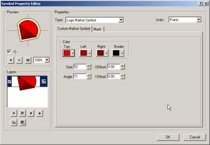
The LogoMarkerPropertyPage is displayed in the Symbol Editor dialog box.
Note that when you open the Symbol Editor for a LogoMarkerSymbol, the dialog box also has a Mask property page - this is displayed automatically if the current Symbol implements IMarkerMask.
Implementing property page interfaces for the LogoMarkerPropertyPage
The interfaces implemented on the LogoMarkerPropertyPage are dependent on the development environment, as described in the earlier section, 'Developing Objects'. In either case, the basic structure of the property page class is similar. In the Applies method, return True if you receive a LogoMarkerSymbol.
Add a property named LogoMarkerSymbol to the Form class. In the SetObjects method, check that you receive a LogoMarkerSymbol object, then set the LogoMarkerSymbol property of the Form to this object.
Add a property called IsPageDirty to the form, and link this to the IComPropertyPage::IsPageDirty property of the LogoMarkerPropertyPage class.
This allows events from controls on the Form to directly change properties of the Symbol. The changes can then be seen in the Preview box after calling IComPropertyPageSite::PageChanged to refresh the dialog box.
Implementing ISymbolPropertyPage
The Size, XOffset, and YOffset properties of a MarkerSymbol are returned and set onto the LogoMarkerSymbol as a printer's Point measurement. However, users may prefer to define the properties of a symbol using a different system of measurement, for example, centimeters or millimeters.
If the ability to use different systems of measurement were encapsulated in the Symbol coclasses themselves, this would not only mean each class contained similar conversion code, but it would complicate the use of the classes.
Therefore, this functionality is added at the property page level by implementing the specialist ISymbolPropertyPage interface.
At the top right hand side of the Symbol Editor dialog box, you can see the Units combo box. When the user changes the Units selection, the property sheet to which the page belongs (in this case the Symbol Editor) calls the active property page to tell it what type of units the user has selected by setting the ISymbolPropertyPage::SymbolUnits property.
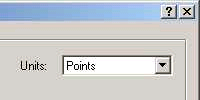
By implementing ISymbolPropertyPage, you can allow a property page to react correctly to changes in the Units combo box of the containing property sheet.
When creating a symbol property page, you must provide the ability to convert from the selected units of measurement to Points.
Add a read-write property to the form called Units, which stores the selected units value in a member variable of the Form. When this property is changed, call the UpdateControls method.
UpdateControls should account for a change in Units by converting the values shown in the Size, XOffset, and YOffset controls to the currently selected unit type - this is because these properties are always stored internally in Points.
Then add the PointsToUI procedure to convert values from Points to the current display units - it returns a formatted string, in the currently selected units, which can be displayed in the Size, XOffset, and YOffset controls.
See Also:
The example codeCustomizing the display
Creating custom symbols
Vertex line symbol example
To use the code in this topic, reference the following assemblies in your Visual Studio project. In the code files, you will need using (C#) or Imports (VB .NET) directives for the corresponding namespaces (given in parenthesis below if different from the assembly name):
- ESRI.ArcGIS.Framework
- ESRI.ArcGIS.Display
- ESRI.ArcGIS.DisplayUI
- ESRI.ArcGIS.Geometry
- ESRI.ArcGIS.System (ESRI.ArcGIS.esriSystem)
| Development licensing | Deployment licensing |
|---|---|
| ArcGIS Desktop Basic | ArcGIS Desktop Basic |
| ArcGIS Desktop Standard | ArcGIS Desktop Standard |
| ArcGIS Desktop Advanced | ArcGIS Desktop Advanced |