Mit der Network Analyst-Lizenz verfügbar.
Schematic diagrams can be generated from solved network analysis layers. The Network Dataset builder is the builder to configure to be able to generate such diagrams. During this exercise, you are going to learn how to create and configure a schematic diagram template to generate diagrams from network analysis layers performed on the ParisMultimodal_ND sample network dataset. This network dataset is stored in the Paris.gdb tutorial geodatabase provided with the ArcGIS Network Analyst extension Tutorials data. The configuration is going to be operated in the SchematicBuilderSamples schematic dataset created during exercise 1.
- Edit the SchematicBuilderSamples schematic dataset stored in the C:\ArcGIS\ArcTutor\Schematics\TutorialSchematicDB geodatabase by browsing to this database using ArcCatalog, right-clicking the dataset, and choosing the Edit menu option
 .
.
Creating a schematic diagram template based on the Network Dataset builder
The first phase consists of creating the schematic diagram template that will be used to generate the diagrams from solved network analysis layers.
- Right-click the SchematicBuilderSamples entry in the Dataset Editor tree and click New Schematic Diagram Template.
A Properties tab for the new schematic diagram template automatically displays on the right side of the Editor Window.
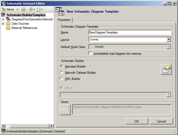
- Type DiagramsFromNetworkDataset in the Name box.
- Choose Network Dataset Builder in the Schematic Builder section.
- Click OK.
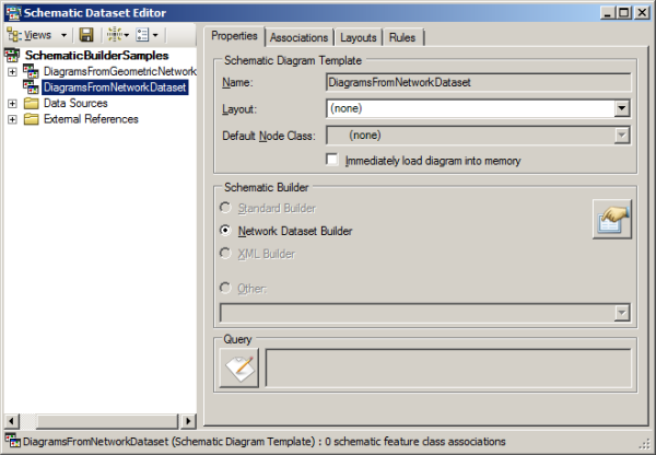
An entry for the DiagramsFromNetworkDataset diagram template automatically displays in the Dataset Editor tree. Three new tabs—Associations, Layouts, and Rules—display on the right side of the Editor Window.
- Click
 Save on the Schematic Dataset Editor toolbar.
- Close the Schematic Dataset Editor.
Generating a schematic diagram from a solved network analysis layer
In this section, you are going to generate your first schematic diagram based on the newly created DiagramsFromNetworkDataset diagram template.
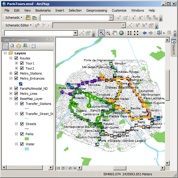
- Open the ParisTours.mxd file using ArcMap.
This file is located in C:\ArcGIS\ArcTutor\Schematics\Schematics_Configuration\Network_Dataset. The features referenced in this map come from the Paris.gdb tutorial geodatabase installed with the ArcGIS Network Analyst extension Tutorials data in C:\ArcGIS\ArcTutor\Network Analyst\Tutorial.
- Make sure the ArcGIS Network Analyst extension is enabled:
- Click Customize on the main menu and click Extension.
- On the Extensions dialog box that opens, check the Network Analyst check box if it is not already checked.
- Close the Extensions dialog box.
- Display the Network Analyst toolbar if it is not already displayed.
- Click the Network Analyst window button
 on the Network Analyst toolbar.
The Network Analyst Window appears.
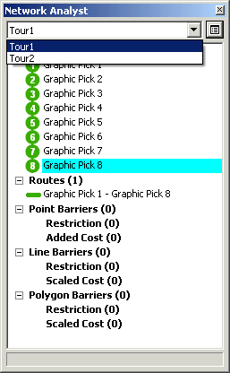
- Select the Tour1 network analysis layer from the drop-down list available on the Network Analyst window.
- Click
 Solve on the Network Analyst toolbar.
- Click the Generate New Schematic Diagram button
 on the Schematic toolbar.
The New Schematic Diagram dialog box opens:
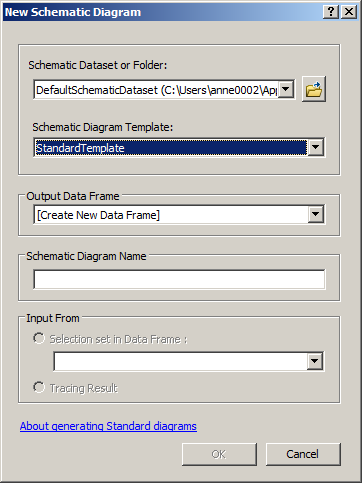
- Specify the schematic dataset in which the generated diagram will be stored:
- Click the browse button at the right of the Schematic Dataset or Folder field.
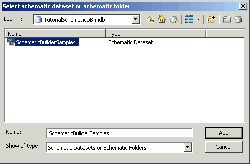
The Select schematic dataset or schematic folder dialog box opens.
- Browse and select the TutorialSchematicDB geodatabase you created in C:\ArcGIS\ArcTutor\Schematics during exercise 1.
- Double-click this geodatabase and select the SchematicBuilderSamples schematic dataset.
- Click Add.
- Click the browse button at the right of the Schematic Dataset or Folder field.
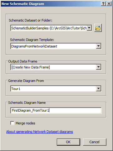
- Choose DiagramsFromNetworkDataset in the Schematic Diagram Template drop-down list.
Note that the Generate Diagram From drop-down list automatically fills with the Tour1 network analysis you solved in step 6. This list contains all the solved network analysis in memory. At that time, Tour1 is the only solved network analysis.
- Type FirstDiagram_FromTour1 in the Schematic Diagram Name field.
At the end of this step, the New Schematic Diagram dialog box content displays, as in the following screen shot:
- Click OK.
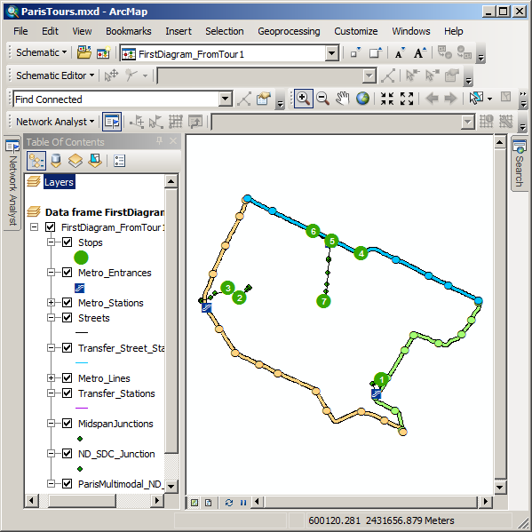
The generation process starts, and the generated diagram displays in a new data frame, which is automatically added in the map document:
