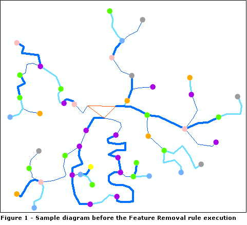
The following samples show the results obtained on a sample diagram when executing Feature Removal rules.
For the diagram template implementing the following sample diagram (Figure 1), Feature Removal rules are going to be specified to
- Remove all the schematic nodes whose type is E; they display with a purple circle (Sample 1).
- Remove all the schematic nodes whose type is E and where all connected links have a particular attribute (Sample 2).
Sample 1—Removing a particular type of schematic nodes
The attributes for the Feature Removal rule to remove all schematic nodes whose Type attribute value is E are specified as follows: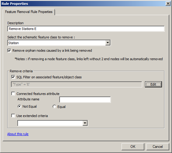
Figure 1.1 shows the result obtained after the diagram update while this Feature Removal rule is active. All the purple schematic nodes are removed.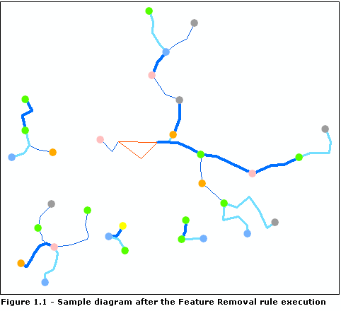
Sample 2—Removing a particular type of schematic nodes when the connected links have a particular attribute
In Figure 1 above, which shows the sample diagram before the rule execution, the width lines of the schematic links display according to the Category value. The purpose in this new sample is to configure the Feature Removal rule so it removes Type E schematic nodes only when all their connected links are in the same category; that is, only when all their connected links display with the same width line. The attributes for this new Feature Removal rule are specified as follows: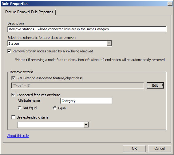
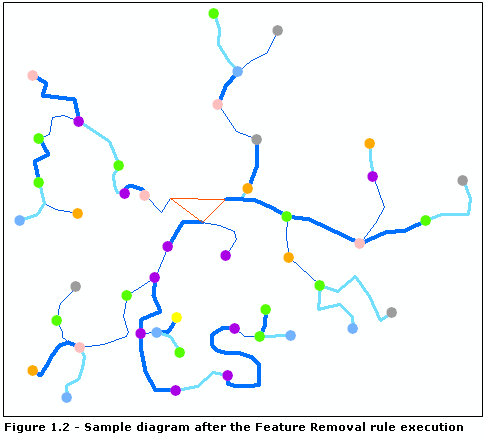
Figure 1.2 shows the result obtained after the diagram update while this new Feature Removal rule is active. The purple schematic nodes for which all connected links have the same Category attribute values have been removed. This allowed the removal of three purple schematic nodes; two with one connection and one with two connected links that are in the same category.