The following samples show Route Node Reduction rule execution results on two diagrams.
With the Network Dataset builder, the diagrams can be generated with or without merging nodes—that is, each network element junction that occurs several times along the resultant route can be represented either by a single merged schematic node or several times in the generated diagram. When a diagram is generated without merging nodes, since all the schematic nodes are nodes with two connections, they are all route nodes. When nodes are merged, the degree of the merged nodes is more than 2 and the Route Node Reduction rule, which only operates on route nodes (degree 2 nodes), doesn't reduce the merged nodes. For a better understanding, the Route Node Reduction rule result samples are shown on two diagrams based on the same solved route network analysis: diagram A, generated without merged nodes, and diagram B, generated with merged nodes.
Figure A shows sample diagram A generated without merging nodes. In this case, each junction and edge that occur several times along the resultant network route is represented by several schematic nodes and links in the generated diagram. The multiplied schematic nodes and links overlap in the diagram.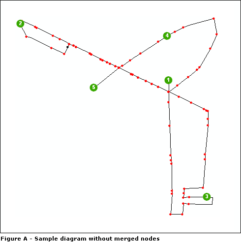
Figure B shows sample diagram B obtained when schematic nodes are merged. In this case, the junctions that occur several times along the resultant network route are not multiplied in the generated diagrams. Only the edges that connect these junctions are multiplied. Using the Separate Overlapping Links schematic layout algorithm on this diagram clearly highlights these merged schematic nodes and their connected links.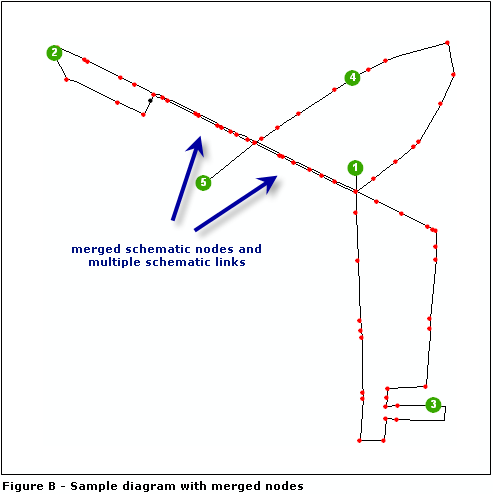
Sample 1—Reducing all route nodes implemented by a given schematic feature class
For the schematic diagram template implementing these sample diagrams, the Route Node Reduction rule is defined to reduce the red route nodes related to ParisMultimodal_ND_Junctions: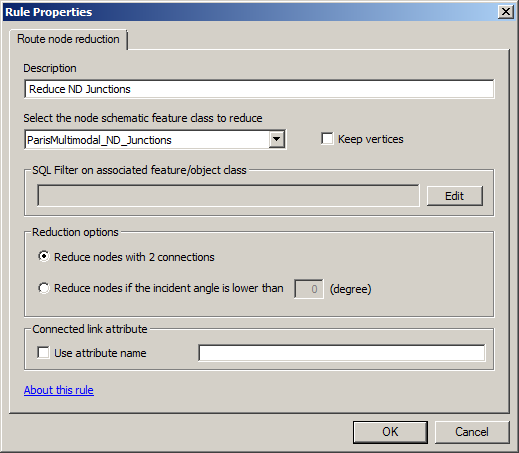
The following figures show the result obtained after updating diagrams A and B while this reduction rule is active: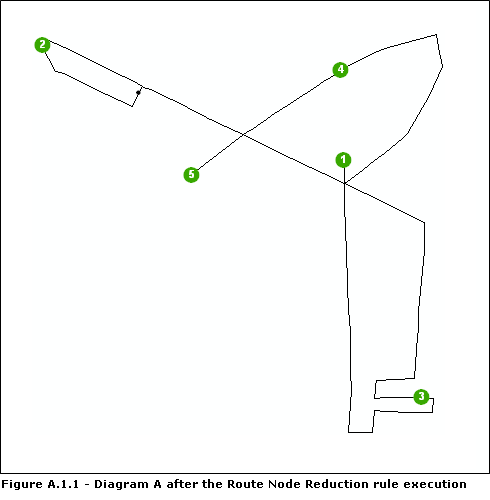
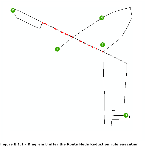
Figure A.1.1 shows diagram A generated without merged nodes after rule execution. Since all the ParisMultimodal_ND_Junctions nodes contained in the diagram were schematic nodes with two connections, the rule reduced all of them. For the diagram generated with merged nodes, figure B.1.1, only the nodes with two connections have been reduced during rule execution. The merged nodes have been kept.
The following figures show diagram B, the one with merged nodes, after it has been laid out using the Hierarchical—Smart Tree schematic layout algorithm: figure B.1.2 shows diagram B content while the Route Node Reduction rule is not active, and figure B.1.3 shows the same diagram while the rule is active.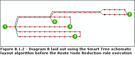
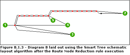
Figure B.1.4 shows the Attr_DriveTime attribute values for the two schematic links currently selected in diagram B while the Route Node Reduction rule is inactive.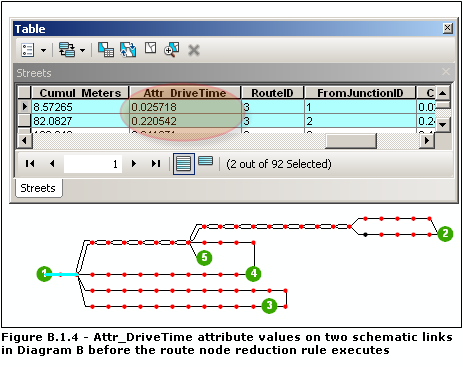
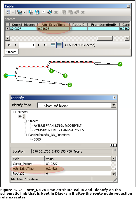
Figure B.1.5 shows information from the single schematic link that is kept after the Route Node Reduction rule is executed.
- The Attr_DriveTime attribute value for this schematic link represents the cumulated Attr_DriveTime values for the related reduced route node and its two incident links.
- When using the Identify tool
 on this schematic link, the Identify dialog box details the reduced schematic features in the window at the top of the dialog box under the entry related to the clicked link. The currently selected Streets schematic link corresponds to the reduced route nodes related to the 3885 ParisMultimodal_ND_Junctions junction and its two incident edges, Streets AVENUE FRANKLIN-D.ROOSEVELT and ROND-POINT DES CHAMPS-ELYSEES.
Sample 2—Reducing route nodes implemented by a given schematic feature class according to their incident angle
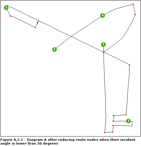
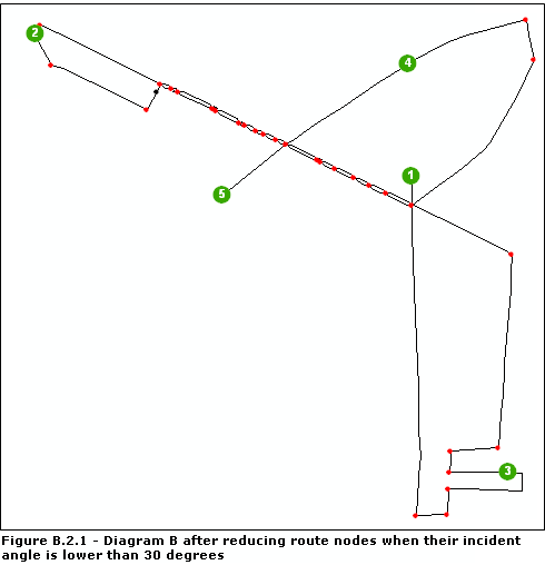
The following screen shots show the results obtained on diagrams A and B while the Route Node Reduction rule is executed to reduce the ParisMultimodal_ND_Junctions route nodes only when their incident links form an angle smaller than 30 degrees.
The Route Node Reduction rule attributes are specified as follows: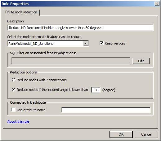
Figures A.2.1 and B.2.1 show the results obtained after the diagrams are updated while this Route Node Reduction rule is active.
