Available with 3D Analyst license.
This topic is intended to provide you with an introduction to the concept of base heights in a 3D viewing environment.
Correctly defining the base height of GIS features in 3D is critical to creating an informative and accurately presented 3D view. However, not all features know their position in 3D space, and this can limit their analytical and editing capabilities. Fortunately, ArcGIS 3D Analyst extension supports many methods for specifying the elevation source of features for display in ArcGlobe and ArcScene.
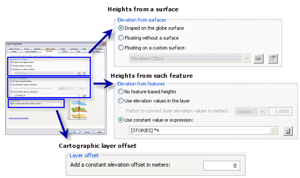
The three main elements for defining feature heights in 3D are:
- Heights from a surface
- Heights from each feature
- Cartographic layer offsets
These elements can be used individually, or they can be combined together in an additive manner. These scenarios will be described in more detail below. As well, the user interface helps you choose by reflecting the possible combinations:
The graphic on the lower right of the dialog box is used to help illustrate the layer's current base height settings.

The position of the filled square box represents the different options. The top two (a and b) and bottom two options (e and f) apply to both ArcGlobe and ArcScene. The central two options (c and d) are only available in ArcGlobe.
The graphic automatically updates as changes are made within the layer property settings. This provides dynamic and visual feedback so you can have a better idea how the 3D view will be displayed.
Heights from a surface
All functional surfaces, such as elevation, atmospheric, or geological layers, have a single height value for each x,y position. This is great information that can be easily leveraged by other feature layers—such as a trees layer—to provide their base height.
There are two methods for linking a feature layer with a surface. You can point a feature layer to either:
| Surface type | Use case |
|---|---|
| This option is supported in both ArcGlobe and ArcScene and requires the feature layer to reference a single, specific surface. This method is useful for smaller extents where a single elevation source exists and where there are stacked surfaces (such as in geology). |
| This option is only supported in ArcGlobe and allows the feature layer to be classified as a layer which is draped on the surface of the globe. ArcGlobe will automatically use other layers in the document to define the surface. This method is particularly useful for larger extents where multiple data sources contribute to the elevation model. |
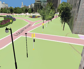
Examples of layers that usually rely on a surface to define their base height (z-values) include trees, street furniture, walking trails, and park boundaries.
Heights from each feature
Some GIS features already know where they are in 3D space. That is, each feature contains a representative height value specific to itself.
There are two methods for incorporating feature-specific heights in the display, and both are available in ArcGlobe and ArcScene. Feature height information can be either embedded in the source data or available as a feature attribute. This is further described in the table below.
| Feature height type: | Use case |
|---|---|
| This option requires that the source data contain z-values, so each vertex in the feature's geometries contain values for x, y, and z. This method is useful for data that was captured in 3D, such as GPS tracking points. |
| This option requires the feature to have one or more attributes that can calculate a height value. This method is useful where height is an important attribute in the data model, such as the altitude of an airplane. A strong understanding of the units being represented in that attribute field is required. Complex expressions are also supported, such as multiplying a floor number with a constant multiplier. |
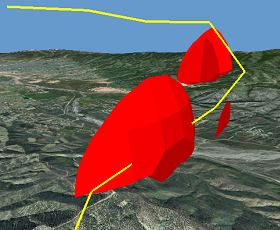
Examples of layers that usually define their own z-values (heights) include airplanes, seismic points, flight paths, and boreholes.
Cartographic layer offset
Sometimes it can be visually effective to apply a vertical offset to the heights of features in 3D. This option is supported in both ArcGlobe and ArcScene as a layer offset property, where all features in the layer are moved up or down by the same, constant value.
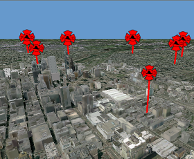
This method is usually employed for cartographic reasons, where the true 3D location of a feature makes it difficult to see within the 3D view. For example, you may want to display the location of important landmarks floating high above a cityscape, rather than having them hidden in their true 3D location.
Examples of layers that can benefit from cartographic layer offsets include fire station icons, school district names, and helipad locations.
Combinations of settings
There are some cases where combinations of base height settings are required. In these cases, set each base height element separately in the Layer Properties dialog box and they will automatically combine when the layer is rendered.
Here are some examples of how combinations of z-values can be applied to your features.
| If you have: | The ideal combination could be: |
|---|---|
| Absolute depths with a cartographic layer offset |
| Draped on a surface with feature-based offset |
| Draped on a surface with a feature-based offset as well as a cartographic layer offset |
Additional, specific topics about base heights when working with 3D Analyst include:
Setting base heights for features in ArcGlobe
Setting base heights for raster layers in ArcGlobe
Setting base heights for features in ArcScene
Setting base heights for raster layers in ArcScene
Understanding the options for setting the height (z-value) for 3D editing
Guidelines for editing features with base height properties in 3D