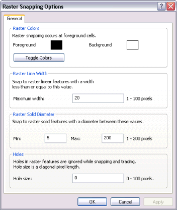
ArcScan supports a separate options dialog box for raster snapping. The Raster Snapping Options dialog box is accessible from the ArcScan toolbar, and it allows you to apply settings that are specific to raster tracing.

The first option on this dialog box is for toggling the raster foreground and background colors. Because raster tracing only works on foreground colors, this tool allows you to switch the desired color to foreground status without having to change the raster layer symbology.
The next option on the dialog box pertains to specifying a maximum raster line width for tracing. Based on the value you enter, you can snap to raster lines that are equal to or less than the maximum line width value. This enables you to control which lines can be snapped to and ultimately vectorized based on their line width.
Similar to the raster line width setting, ArcScan also provides a setting for snapping to solids. Solids are a series of raster cells that represent circular features. In some cases, elements in the raster qualify as a circle but are not in the scope of the vectorization (for example, periods and dots). You can specify a minimum and maximum range for solid diameters. Any solid in which its diameter falls within this range is recognized as a solid and is available for snapping.
ArcScan provides a way to ignore holes that exist in raster linear elements when tracing with the Vectorization Trace tool. Hole size is measured as the diagonal distance of the background cells in pixels. Holes that are less than the specified size are ignored, and the Vectorization Trace tool continues to trace the connected cells. Holes can appear in areas of the raster that represent lines due to poor resolution.