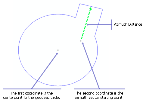
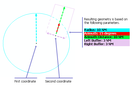
The Keyhole (Two Points - Azimuth) function uses the distance from the second coordinate, the azimuth vector starting point, and the Azimuth Distance parameter to determine how much the rectangular part of the keyhole will extend.
The first coordinate is the centerpoint for the geodesic circle, typically an airport reference point, and is used to create the circular part of the keyhole. The second coordinate is the azimuth vector starting point, typically a Navaid, and is used to create the rectangular part of the keyhole.


- Start ArcMap.
- On the menu bar, click Customize > Toolbars > Production Feature Builder.
- Click the Feature Builder button
 on the Production Feature Builder toolbar.
The Feature Builder window appears.
- If the scratch dataset has not been added to the table of contents, click the Add Scratch Data Layers button
 at the top of the Feature Builder window.
The dataset is added to the map using the current spatial reference.
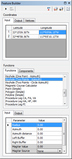
- Choose Keyhole (Two Points - Azimuth) in the list on the Functions tab.

- Define a coordinate for the start point of the polyline by doing one of the following:
- Click the Pinprick tool
 on the Production Feature Builder toolbar and click on the map
 - Type the coordinates in the cells on the Input tab in the Coordinates area.
- Click the Pinprick tool
- Repeat step 6 to define a coordinate for the azimuth vector starting point.
- Click the cell next to Radius and type a value for the radius.
This is the radius from the first coordinate that creates the circular part of the keyhole. The default unit is Nautical Miles.
- Click the cell next to Azimuth and type the azimuth value.
The azimuth is the angle from the second coordinate at which the keyhole is going to be created. The default unit is degrees.
- Click the cell next to Azimuth Distance and type a value that represents the distance the angle should extend for the rectangular part of the keyhole.
This is the distance from the second coordinate to the end of the rectangular part of the keyhole for the angle at which the keyhole is going to be created. The default unit is Nautical Miles.
- Click the cell next to Left Buffer and type the value for the left buffer.
This is the amount of space that should exist on the left side of the keyhole. The default unit is Nautical Miles.
- Click the cell next to Right Buffer and type the value for the right buffer.
This is the amount of space that is going to exist on the right side of the keyhole. The default unit is Nautical Miles.
- If necessary, click the cell next to MagVar Value and type a value for the magnetic variation.
This can be a specified value or from a field defined in the MagVar Source parameter. The default unit is degrees.
- If necessary, click the drop-down arrow next to MagVar Source and choose a source for the magnetic variation.
This is the source of the magnetic variation value.
- If necessary, click the drop-down arrow next to MagVar Year and choose a different year for the World Magnetic Model.
This is the year associated with the magnetic variation value.
- Click the Execute button
 .
.
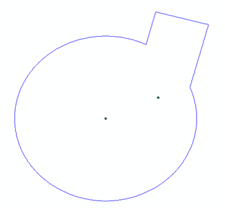
The keyhole geometry appears in the Scratch Data layer.