The advanced linear referencing system (ALRS) extends the geodatabase to provide additional capabilities for linear referencing, including support for multiple linear referencing methods (LRMs), event location management, and a time-aware linear referencing system (LRS).
-
Right-click the target geodatabase and click
New > Advanced Linear Referencing System.
- In ArcCatalog, the geodatabase is in the Catalog tree.
- In ArcMap, the geodatabase is in the Catalog window.
The Advanced Linear Reference System Setup wizard appears.
- Click Next.
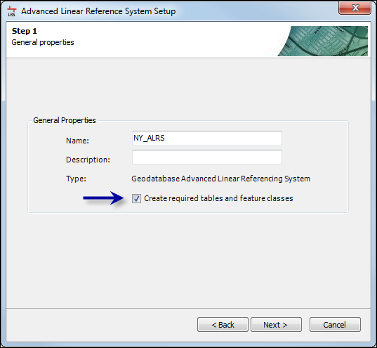
- Name the new ALRS and provide a brief description.
- Click Next.
The Step 2 of 8, Minimal schema dialog box appears.
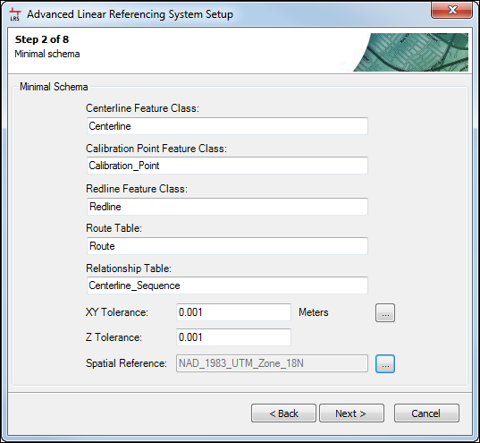
- Name the minimum schema items and select the tolerance and spatial reference.
- Choose the name for each minimum schema item.
- Select the x-y- and z-tolerance for the centerline, calibration point, and redline feature classes.
Enter the values by typing in the text boxes for X-Y Tolerance and Z Tolerance, or by selecting the tolerance values from an existing feature class, such as your source routes, by clicking the ellipsis (...) button to the right of the text boxes.
The tolerance settings selected during this step are used for the LRS Network feature class for each created network. These tolerance settings also determine the level of precision and number of decimal places displayed for measures on your network. If you are not creating the minimum schema items during ALRS creation, ensure the spatial reference and tolerance settings for your centerline, calibration point, and redline feature classes match since they will apply to any created LRS Networks.
- Select the spatial reference of your required tables and feature classes by clicking the ellipsis (...) button next to the Spatial Reference field.
If you selected an existing feature class for your x-y and z tolerance in the previous step, the spatial reference of that feature class is automatically selected for you. The spatial reference of your ALRS should match the spatial reference of your source polyline route feature class.
- Click Next.
The Step 3 of 8, Schema dialog box appears.
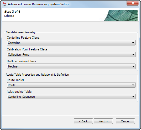
- Map the ALRS schema to the proper data elements.
See ALRS data model to learn about the data elements used in the ALRS.
- Click Next.
The Step 4 of 8, Route relationships dialog box appears.
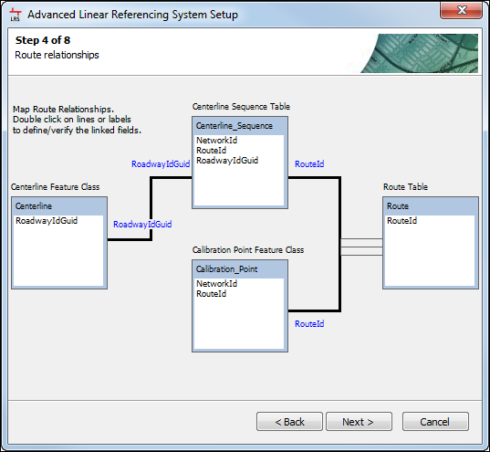
- Define the route relationships to use in the ALRS schema.
- To change the fields serving as the link between the Centerline feature class and Centerline Sequence table, Centerline Sequence table and Route table, or Calibration Point feature class and Route table, double-click the black connector lines on the Route relationships page of the Advanced Linear Reference System Setup dialog box (step 3 of 7 or 4 of 7) to display the Edit Relationship dialog box.
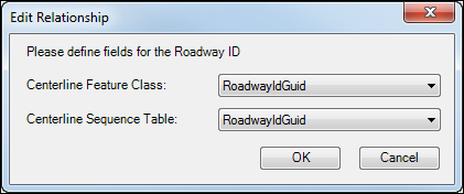
- Use the field drop-down arrows to set the primary and foreign keys for the relationships between routes, centerlines, and calibration points.
The fields you select link the geometry of the centerline feature class to the routes in the route table via the centerline sequence table to ensure the LRS Network has geometry and routes. Additionally, it ensures the calibration points are correctly linked with the route table and the LRS Network once they are created. See ALRS data model to learn about the relationships in the ALRS.
- Click OK.
- To change the fields serving as the link between the Centerline feature class and Centerline Sequence table, Centerline Sequence table and Route table, or Calibration Point feature class and Route table, double-click the black connector lines on the Route relationships page of the Advanced Linear Reference System Setup dialog box (step 3 of 7 or 4 of 7) to display the Edit Relationship dialog box.
- Click Next.
The Step 5 of 8, Field Mapping dialog box appears.
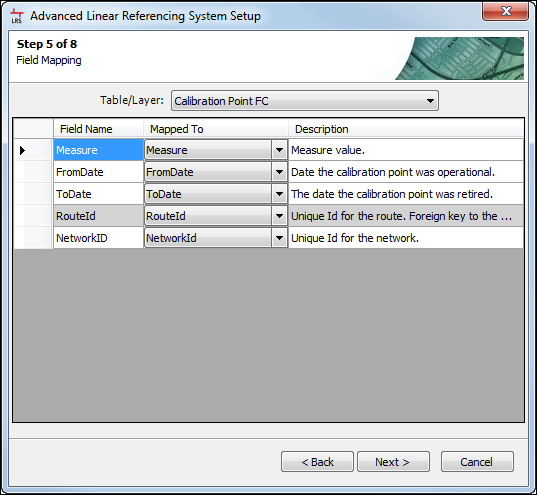
- Map fields to ALRS data elements.
- Choose ALRS data elements using the Table/Layer drop-down arrow.
- Map the ALRS fields to the data element field names using the Mapped To drop-down arrow.
See ALRS data model to learn more about the ALRS data elements.
- Click Next.
The Step 6 of 8, Lock and Notifications dialog box appears.
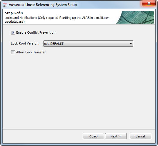
- If the ALRS needs conflict prevention, check the Enable Conflict Prevention check box and choose the lock root version from the list of versions in the Lock Root Version drop-down list. If lock transfers between users will be allowed, check the Allow Lock Transfer check box. For more information on conflict prevention, see Conflict prevention.
This step is only available if the ALRS is created in a multiuser geodatabase environment.
The Step 7 of 8, Elevation Dataset Configuration
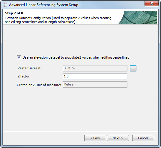
- If a digital elevation model or similar raster dataset is going to be used to calculate the Z values of centerlines when creating and editing them in Roads and Highways, configure the Elevation Dataset Configuration. For more information about using Z values on centerlines, see Elevation data on routes.
This step is not required if an elevation model is not going to be used with your ALRS.
- Check the Use an elevation dataset to populate Z values when editing centerlines box if an elevation model is going to be used.
- Click the ellipsis (...) button to the right of the Raster Dataset to select your elevation model.
- Type the Z factor for the elevation model in the text box.
- The Centerline Z unit of measure is populated automatically based on the spatial reference of the centerlines in the ALRS.
- Complete the ALRS setup wizard.
- Click Next.
- Click Finish to finish creating the ALRS and close the wizard.
The Question message appears asking if you want to create a new network.

- Choose one of the options and close the ALRS setup wizard.
- Click Yes to create a new network.
- Click No to close the ALRS setup wizard and return to ArcMap or ArcCatalog. If the networks in your ALRS use a concatenated route ID or contain coded value domains or subtypes, choose this option and follow the steps in Using concatenated route identifiers.
- Click Next.