A legend tells a map reader the meaning of the symbols used to represent features on the map. Legends consist of examples of the symbols on the map with labels containing explanatory text. When you use a single symbol for the features in a layer, the layer is labeled with the layer's name in the legend. When you use multiple symbols to represent features in a single layer, the field you use to classify the features becomes a heading in the legend, and each category is labeled with its value.
Legends have patches that show examples of the map symbols. By default, the legend patches are points, straight lines, or rectangles that match the map symbols. You can customize the legend patches, for example, so areas are represented with patches of another shape, or rivers are drawn with a sinuous rather than a straight line.
A quick tour of the Legend Wizard
The Legend Wizard provides an easy, quick way to add a legend to your map. The wizard allows you to
- Choose which map layers you want to be part of the legend.
- Set the number of columns in the legend.
- Create and symbolize a legend title.
- Create and symbolize a border and background for the legend.
- Customize the shape and size of legend patches.
- Set the spacing between legend elements.
When you first access the wizard, you will see the list of layers in your map that will make up the legend.
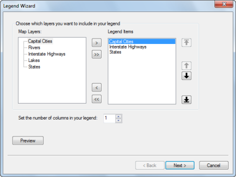
Not all layers need to be in the legend. You have the option to remove any of the layers listed. You can reorder the layer list as you see fit. This reordering does not affect layer ordering in the table of contents. This panel of the wizard also provides options to set the number of columns in the legend. The wizard does not provide options to determine where columns begin. You can further refine your columns by modifying the legend after it has been created using the options on the Items tab of the Legend Properties dialog box.
The next panel provides a place for you to enter a legend title.
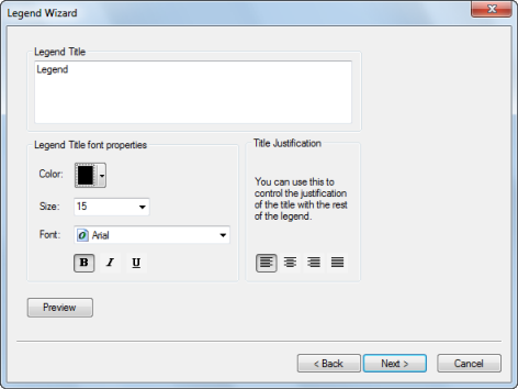
Along with typing in the title text, you can choose the color, size, font, and justification of the text.
The next panel offers choices to customize a border, background, and drop shadow for the legend.
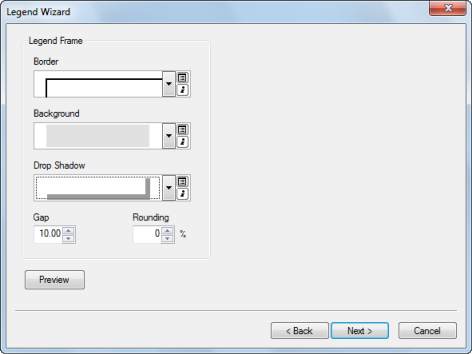
The next to last panel gives you the opportunity to set patch properties for line and polygon symbols.
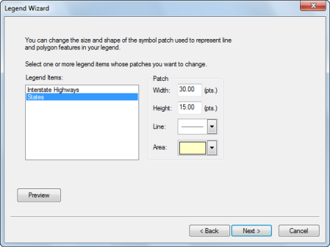
Here, you can set the width, height, and shape of the patch for line or polygon features.
Learn more about working with legend patch shapes
The last panel allows you to specify the spacing between legend elements.
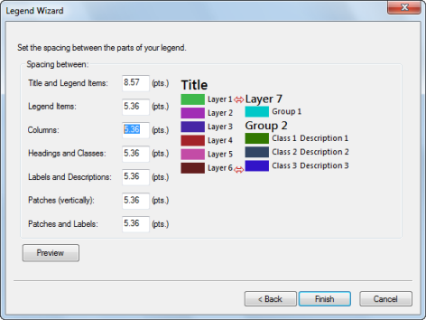
As you click each spacing input box, the spacing indicator (in red) in the image to the right will adjust to show you where the spacing will be adjusted.
Transparency in legends
If you have layers with transparency in your map, ArcMap simulates the transparent colors in your legend. When layers in a data frame are made transparent, the table of contents and the legends in layout view automatically use lighter colors to reflect transparency.
The option to simulate transparency in legends is set on the General tab on the Data Frame Properties dialog box. When this option is turned on, solid, bright red polygons drawn on a layer appear in the legend as a light red or pink, depending on the percentage of transparency applied to the layer. However, with the Simulate transparency option off, the legend still shows the solid red polygon symbol, even though the polygons don't appear red on the map because the layer is transparent.
In addition, you can convert the legend to graphics and manually specify the legend patch colors. Using the Eye Dropper tool, you can obtain the exact RGB value of a pixel and use that color for the legend patch.
Modifying legend properties
Using the Legend Properties dialog box, you can
- Change the wording, symbology, and position of the legend title.
- Change properties for patches.
- Change the reading orientation.
- Adjust the spacing between legend elements.
- Change the presentation style.
- Add or remove columns.
- Change text symbology for selected items.
- Determine the interactive behavior of the legend through its connection with the map.
- Determine the interactive behavior of the legend with the current map extent.
The Legend Properties dialog box has five tabs: General, Items, Layout, Frame, and Size and Position.
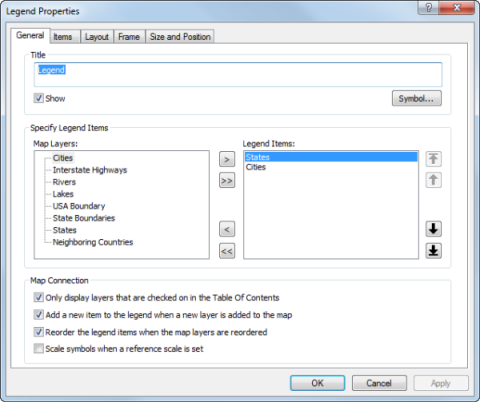
The General tab provides a way to customize the legend title, specify legend items, and set the map connection properties.
Currently, only one position for the title, above, is supported. You can convert the legend to graphics and rearrange legend components manually if you want to reposition the title. You can also choose not to include a title as part of the legend and create a title as an independent graphic element.
To specify which layers will appear as items in your legend, use the buttons between the lists of map layers and legend items. Layers in your map that can be legend items will appear in the Map Layers list. The layers listed in the Legend Items list reflect the actual make up of your legend. To reorder one or more items in the legend, select the items in the Legend Items list, and click the buttons to the right of the list to move them up and down or to the top or bottom of the list.
There are also four options available to adjust the behavior of the legend based on changes made to the map:
- Only display layers that are checked on in the table of contents.
- Add a new item to the legend when a new layer is added to the map.
- Reorder the legend items when the map layers are reordered.
- Scale symbols when a reference scale is set.
You can choose to only display layers that are checked on in the table of contents. If a layer's visibility is turned off, it will automatically be removed from the legend; otherwise, layers will be shown in the legend whether or not they are visible on the map. You can also have the legend add a new item to the legend automatically when a new layer is added to the map. Another option is to reorder legend items automatically whenever the map layers are reordered in the Table of Contents. Lastly, you can choose to scale symbols in the legend when a reference scale is set in the map. This will match the size of line and point symbols in the legend to the size of line and point symbols on the map. This only applies when the map has a reference scale. Without a reference scale set, the size of symbols in the map and the legend will remain constant.
On the Items tab, you can customize individual legend items, change text symbology, change how items interact with the current map extent, and change column settings at the item level.
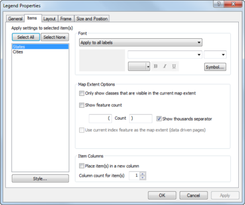
While working in the Items tab, you can apply changes to one or more items at a time. When you select multiple items from the list, the changes you make will apply to all the selected items. Settings you do not change will remain the same as they were for each individual item.
To change the text symbol used by some or all of the items, use the font controls next to the item list. You can apply these changes to all the text associated with the selected items, or just to particular text items. These include the layer name, the heading, the label, and the description. Use the drop-down menu to select which text items you would like to change.
You can also modify all the text symbology in the legend at once by using the font controls on the Draw toolbar while the legend is selected in your layout.
The Map Extent Options allow you to control how eligible legend items interact with the current map extent. If the Only show classes that are visible in the current map extent check box is checked, a legend item class will only appear in the legend if a feature from that class is in the current extent. If no features from that legend item are in the current extent, the entire item will be removed from the legend. You can also add feature counts to your legend by checking the Show feature count check box. The number of features from that legend item class that are in the current extent will appear after that class' label. If a legend item does not have labels, the count will appear after the patch. You can set the text that will appear before and after the feature count by typing in the text boxes. You can also set whether or not you would like to display a thousands separator by checking or unchecking the Show thousands separator check box. If Data Driven Pages is enabled, you can check the Use current index as the map extent (data driven pages) check box to use the extent of the current index feature as the current map extent. By default, the current extent of the data frame is used. If the data frame is clipped, the current clip shape will be used as the extent. Layers that are excluded from the clip will still use the full extent of the data frame.
This tab is also where you can control the number of columns in your legend. You do this by placing items in new columns and setting the number of columns for each item. To place an item in a new column, select it from the list and check the Place in new column check box. You can also enter the number of columns you want to use for each legend item. Use these properties on individual legend items to achieve your overall desired column configuration.
To change the legend item style, double-click the item listed in the Legend Items list box. This takes you to the Legend Item Selector dialog box.
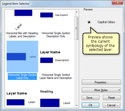
Here, you can select and preview the legend style you want to use for the chosen legend item. As you select an arrangement from the left, you will see a preview on the right. To make further modifications, click Properties. This brings up the Legend Item Properties dialog box. Using this dialog box, you can further customize the arrangement and appearance of legend items.
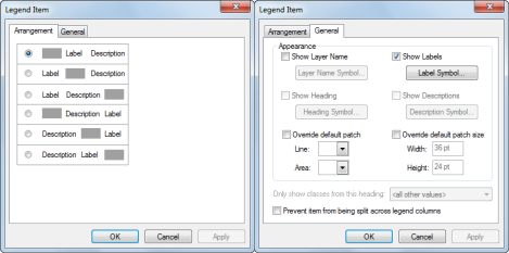
The Arrangement tab provides six options for the arrangement of the patch, label, and description. The General tab allows you to hide, display, and change the text symbology of the layer name, labels, headings, and description. You can also override the default patch for line and polygon features. Other options on the General tab include the ability to show classes from a specific heading if the layer has been divided under headings on the Symbology tab of the Layer Properties dialog box and to prevent items from being split across legend columns.
On the Layout tab, you can set the default legend patch, set the spacing between legend elements, set the fitting strategy, and set the legend to read right to left.
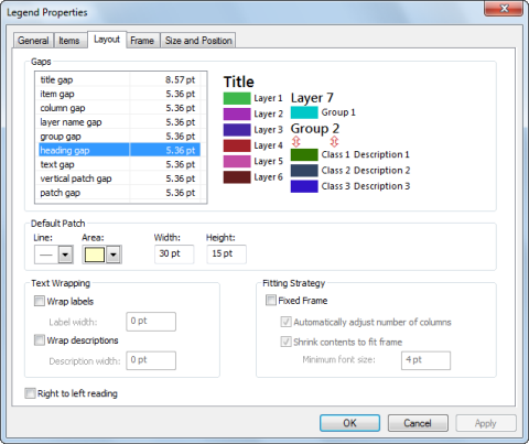
You can set the default width, height, and shape of the patch for line and polygon features for all legend items. To override the default legend patch, open the Legend Item Properties dialog box for an item and check Override default patch.
Learn more about working with legend patch shapes
You can also specify the spacing between legend elements. As you click each spacing input box, the spacing indicator in the image to the right will update to show you where the spacing will be adjusted.
After applying these values, the legend will resize to meet them. However, if you resize the legend afterwards the values will adjust accordingly.
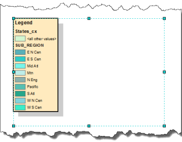
You can also adjust the way legend items fill the bounding box. By default, legend items will take up the entire frame. Legend items will grow or shrink as you resize the legend frame and the bounding box will grow or shrink when items are added or removed from the legend. However, if the Fixed Frame option is selected, the frame size will remain fixed, and as legend items are added or removed, they will adjust to fit inside. It is important to remember that this means it will try to make the legend as compact as possible, not that it will try to take up the entire bounding box. Instead of resizing legend item elements to fill the frame; font size, default patch size, and gap measurement values will be used as maximum values. After the entire frame is taken up using these values, legend items will begin to drop. The following symbol will appear if any items have been dropped from the legend  .When fitting the legend into the frame, column settings for individual legend items will be respected unless Automatically Adjust Number of Columns is checked. With Automatically Adjust Number of Columns checked, column settings for individual items will be overridden and a new column will be made whenever the entire height of the legend frame is taken up.
If Shrink Contents to Fit is checked, legend contents will shrink in an attempt to fit more items on the legend until a minimum font size is hit. Once this font size is hit by any legend text item, the legend will begin dropping legend items that do not fit.
When a border, background, or drop shadow is added to a legend with Fixed Frame enabled, they will resize to surround the legend items and not the bounding box.
You can enable text wrapping on labels and descriptions by checking the boxes Wrap labels and Wrap descriptions, respectively, and setting maximum width values. The label and description widths will be used along with patch and gap measurements to set your total column width. If a column does not have labels or descriptions, the label and description widths will not be added to the total width of those columns. Text will wrap after it reaches the limit using standard character breaks. If a piece of text doesn't fit, it will be truncated with an ellipsis. The measurements you set for description and label width will remain constant even if you resize the legend frame. They will not adjust proportionately like other measurements.
By default, the legend is set up to read left to right. To have it read right to left, check the Right to left reading check box.
Finally, the dialog box contains two standard tabs for setting the frame (border and background) and the size and position of the legend.
Converting map elements to graphics
You might want to convert a map element, such as a legend, to graphics if you want more precise control over each item that composes the map element.
It is important to note that once you convert a map element into a graphic, it is no longer connected to its original data and will not respond to changes made to the map. For instance, with a legend element, if you decide to add another layer to the map after the legend has been converted to a graphic, the legend will not automatically update. It will have to be deleted and rebuilt again using the Legend Wizard. Therefore, it is a good idea to convert elements to graphics only after your map's layers and symbology are finalized.
The image below shows a legend that has been converted to a graphic:
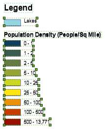
You can further ungroup the legend graphics so the individual elements (the patches, text, and so on) that compose the legend can be edited individually.
How to change the number of columns in your legend
Though you can set the number of columns in your legend when you are first creating it using the Legend Wizard, you may find that you want to further refine your columns. You can do this using legend properties.
- Double-click the legend to bring up the Legend Properties dialog box.
- Select the layer from Legend Items that you want to start a column.
- Check the Place in new column check box.
- Repeat this for each additional layer in which you want to start a column.
How to change the properties for a single legend item
- Double-click the legend to bring up the Legend Properties dialog box.
- Click the Legend tab on the Legend Properties dialog box.
- Right-click the item from Legend Items in which you want to edit and click Properties.
- Make your changes using the Arrangement and General tabs.
How to turn on transparency simulation in your legend
- Right-click the data frame in the table of contents and click Properties.
- Click the General tab.
- Check the Simulate layer transparency in legends check box.
Optionally, uncheck the Simulate layer transparency in legends check box if you do not want transparency simulation in your legend.
Adding mixed-format text to legend descriptions
- Edit the class descriptions and enter some formatted text. To add a description, right-click the layer to which you want to add descriptive text in the table of contents, click Properties, then click the Symbology tab on the Layer Properties dialog box.
- If you are using the Single symbol method, click the Description button. If you are using a drawing method other than Charts, right-click a symbol after you have specified its symbology options and click Edit Description.
- The text you enter here appears next to that symbol in the legend; the text won't appear in the table of contents. If you want your description to be on more than one line, insert a line break by pressing CTRL+ENTER while on the Description for Legend dialog box.
- Click OK on the Layer Properties dialog box to apply the symbology to your layer.