Available with 3D Analyst license.
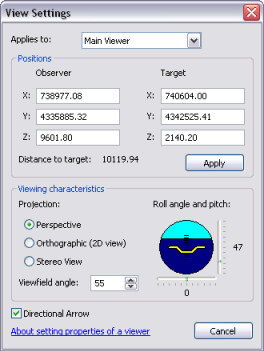
The View Settings dialog box in ArcScene offers several controls to customize your 3D view.
You can access these controls by clicking View > View Settings. All of the options can be applied to the main 3D viewer, or any additional 3D viewer windows which have been opened.
Learn more about additional 3D view windows in ArcScene
The View Settings dialog box can be open while you continue to interact with the 3D view. This is useful for both providing feedback on your current settings, or allow you to update the view directly from the controls.
View setting options
The controls you can adjust for the 3D view include:
- Positions—You can specify where the camera is pointing by adjusting the coordinates of the observer or target.
- Projection options—You can switch between perspective, orthographic (2D) views, and a stereo viewing mode which is only available in ArcScene.
- Viewfield angle—You can adjust the active viewer's virtual camera angle towards either a zoomed in effect or a wider angle to let you see more.
- Increasing the angle also increases the distortion until you have something that appears as looking through a fish-eye, or wide-angle lens.
- Roll angle and pitch—You can change the roll and pitch angles of the viewer.
- On-screen graphic—You can activate the Directional Arrow navigation graphic.

Specifying the coordinates of the observer or target
You can change the position of the camera (observer) and its target by typing in x-, y-, and z-coordinates.
If you have multiple viewer windows open, you must select the appropriate viewer from the drop-down list at the top of the View Settings dialog box.
Changing the projection
By default, the projection option is set to perspective. However, you also have the option of changing the view to orthographics so that the observer is looking straight down from above. The scene looks two-dimensional (2D), like a map.
Setting the view to 2D in ArcScene
When the scene is in orthographic projection, you can only edit the observer's position, not the target's.
Click View > View Settings and select the viewer you want to change if you have multiple open. Select the orthographic (2D view) option, and you will see the scene view change, so it no longer has a perspective distortion of scale.
Keep in mind that when working in orthographic view, extruded points are not visible. If you need to see extruded point data in an orthographic view, copy and paste the layer in the scene and turn off extrusion for the copy.
Setting the view to stereo mode
Stereo viewing is unique to ArcScene. It provides added depth and realism to your 3D views and can be set up in three different methods. See About viewing in stereo mode for a detailed explanation about using the three methods and how to set up the display for each of those methods.
Changing the roll and pitch of the view
Roll and Pitch are rotation angles around the line between the Observer and Target positions. In ArcScene, roll and pitch are only applicable in perspective viewing. If you have the viewer set to Orthographic, the pitch and roll controls are disabled.
Using the View Settings dialog box, there are sliders for both roll and pitch angles which you can interactively drag, adjusting the horizon.
Roll is rotation around the line between the observer and target. Positive values will roll the camera to the right. Negative values will roll the camera to the left. A value of zero (0.0) is horizontal. For example, a plane rolls to the left when it banks to make a left turn on approach into a runway.
Pitch is rotation around a vertical axis. It is the angle in degrees of the observer relative to the target. Positive angles place the observer above the target, looking down. Negative values have the observer looking up. A value of zero (0.0) places the observer at the same height as the target. For example, a ship pitches forward and backward as the bow or the stern dips when sailing into and out of waves.
Using the directional arrow
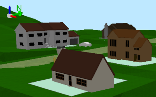
You can help orient yourself within the 3D view by enabling the directional arrow navigation graphic. The three-point arrow represents the x-, y-, and z-axes of your 3D space. The larger, green arrow represents the y-direction, or up in a 2D map. In projected coordinate systems, this green arrow effectively points North and an N character will be displayed to indicate this. The directional arrow always displays in a fixed location in the upper-left corner of the display.
