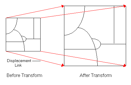
Transformations move or shift data within a coordinate system. They are often used to convert data from unknown digitizer or scanner units to real-world coordinates. Transformations can also be used to convert units within a coordinate system, such as converting feet to meters. To convert data between coordinate systems, such as geographic to UTM, you should project the data instead.
The transformation functions are based on the comparison of the coordinates of source and destination points, also called control points, in special graphic elements called displacement links. For transformations, the from and to locations of links are used to construct the transformation formulas. You can create these links interactively, pointing at known source and destination locations, or by loading a link text file or control points file.
When creating links for transformations, you are trying to match the same location in the source and destination locations. For example, you may have a roads layer you are trying to transform or shift to the location of other data that may contain an aerial photograph. When you create displacement links, the from end could be placed at an intersection in the roads layer while the to end should be placed at the corresponding intersection on the image. Links do not have to start or end on features. Often, the distance between the from and to locations can be quite large.

By default, ArcMap supports three types of transformations: affine, similarity, and projective.
Affine transformation
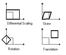
An affine transformation can differentially scale the data, skew it, rotate it, and translate it. The graphic below illustrates the four possible changes.

The affine transformation function is
x’ = Ax + By + C
y’ = Dx + Ey + F
where x and y are coordinates of the input layer and x’ and y’ are the transformed coordinates. A, B, C, D, E, and F are determined by comparing the location of source and destination control points. They scale, skew, rotate, and translate the layer coordinates. This method requires a minimum of three links. This is the recommended choice for most transformations.
The affine transformation requires a minimum of three displacement links.
Similarity transformation
The similarity transformation scales, rotates, and translates the data. It will not independently scale the axes, nor will it introduce any skew. It maintains the aspect ratio of the features transformed, which is important if you want to maintain the relative shape of features.
The similarity transform function is
x’ = Ax + By + Cy’ = -Bx + Ay + Fwhere
A = s * cos t
B = s * sin t
C = translation in x direction
F = translation in y direction
and
s = scale change (same in x and y directions)
t = rotation angle, measured counterclockwise from the x-axis
A similarity transformation requires a minimum of two displacement links. However, three or more links are needed to produce a root mean square (RMS) error.
Projective transformation
The projective transformation is based on a more complex formula that requires a minimum of four displacement links.
x’ = (Ax + By + C) / (Gx + Hy + 1)
y’ = (Dx + Ey + F) / (Gx + Hy + 1)
This method is used to transform data captured directly from aerial photography. For more information, refer to one of the photogrammetric texts listed in the Spatial Adjustment help references.
Understanding residual and root mean square
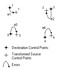
The transformation parameters are a best fit between the source and destination control points. If you use the transformation parameters to transform the actual source control points, the transformed output locations won't match the true output control point locations. This is called the residual error; it is a measure of the fit between the true locations and the transformed locations of the output control points. This error is generated for each displacement link.
A root mean square error is calculated for each transformation performed and indicates how good the derived transformation is. The following example illustrates the relative location of four destination control points and the transformed source control points:

The RMS error measures the errors between the destination control points and the transformed locations of the source control points.

The transformation is derived using least squares, so more links can be given than are necessary. Specifying a minimum of three links is required to produce a transformation that results in an RMS error.
Generally, the more links you place for a transformation, the more accurate it will be. You can check the accuracy of the transformation by viewing the RMS errors in the link table.
Blind transformations
Sometimes you will need to perform an adjustment, usually a transformation, where you have no data at the destination location and cannot interactively place the to end of a displacement link. For example, you may have digitized some data and want to transform it from digitizer units to real-world coordinates. In this case, you will probably know the real-world coordinates of some feature locations in your data such as a road intersection or well location.
You can still set up the transformation by creating displacement links with the from end at known locations and the to end at temporary points in space. You can then use the link table to edit the destination coordinates of these links to be the corresponding real-world locations.