Available with 3D Analyst license.
A triangulated irregular network (TIN) surface can be generated from either surface source measurements or by converting another functional surface to a TIN surface.
You can create a TIN surface from features, such as points, line, and polygons, that contain elevation information. Use points as spot locations of elevation data. Use lines with height information to enforce natural features, such as lakes, streams, ridges, and valleys. Finally, use polygons to clip the TIN to your area of study.
A TIN surface can also be created from other functional surfaces, such as raster or terrain datasets. You may want to convert your raster surface to a TIN to add additional features, such as streams and roads,to the surface model. To convert a raster dataset to a TIN, use the Raster To TIN geoprocessing tool. For more information on how to convert rasters to TINs, see: Creating a TIN surface from raster data.
When working with the multiresolution terrain dataset, you may want to convert a portion of your terrain dataset into a TIN surface to work with a smaller area of interest at a specific pyramid level. To convert a TIN to a terrain dataset, use the Terrain To TIN geoprocessing tool. For more information on how to convert terrain datasets to TINs, see: Creating a TIN surface from a terrain dataset. Keep in mind that a file-based TIN has an effective size limit. The maximum allowable size of a TIN varies relative to free, contiguous, memory resources. The largest size achievable under normal operating conditions with Win32 is 10 to 15 million nodes. Regardless, it's strongly recommended to cap the size at a few million for the sake of usability and performance. Anything larger than this is best represented using a terrain dataset.
Several different vector data sources can contribute to a TIN surface. As part of TIN surface design, you establish the role of each data source in the TIN and how each data source is used.
Here is a brief review of the surface feature types that can be used to build a TIN surface. For more information on how to build a TIN from vector source measurements and convert terrain datasets to TINs, see: Creating TIN surfaces from vector data.
Mass points
Mass points are point height measurements; they become nodes in the TIN network. Mass points are the primary input into a TIN and determine the overall shape of the surface.
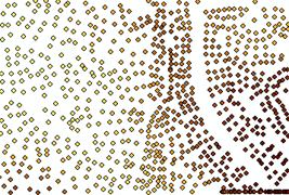
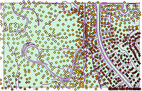
TINs allow you to model heterogeneous surfaces efficiently by including more mass points in areas where the surface is highly variable and fewer in places where the surface is less variable. The example below shows mass points categorized by the height attribute.
Breaklines and hulls
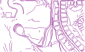
Breaklines, shown below, are lines with or without height measurements. They become sequences of one or more triangle edges. Breaklines typically represent either natural features, such as ridgelines or streams, or built features, such as roadways. There are two kinds of breaklines: hard and soft.
Hard breaklines
Hard breaklines represent a discontinuity in the slope of the surface. Streams and road cuts could be included in a TIN as hard breaklines. Hard breaklines capture abrupt changes in a surface and improve the display and analysis of TINs.
Soft breaklines
Soft breaklines allow you to add edges to a TIN to capture linear features that do not alter the local slope of a surface. Study area boundaries could be included in a TIN as soft breaklines to capture their position without affecting the shape of the surface.
Hulls
Polygons represent surface features with area—such as lakes—or boundaries (hulls) of separately interpolated areas.
Hulls could define the shores of individual islands in an archipelago, or the boundary of a study area.
Polygon surface feature types
There are four polygon surface feature types:
- Clip polygon interpolationons, shown below, define a boundary for the TIN surface. Input data that falls outside the clip polygon is excluded from the interpolation and analysis operations—for example, contouring or volume calculations.
- Erase polygons define a boundary for interpolation. Input data that falls within the erase polygon is excluded from the interpolation and analysis operations—for example, contouring or volume calculations.
- Replace polygons set the boundary and all interior heights to the same value. A replace polygon could be used to model a lake or an area on a slope excavated to a level surface.
- Fill polygons assign an integer attribute value to all triangles that fall within the fill polygon. The surface height is unaffected, and no clipping or erasing takes place.
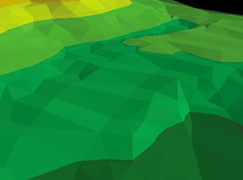
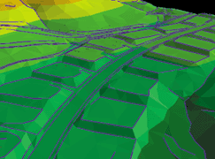
Polygon features are integrated into the triangulation as closed sequences of three or more triangle edges. Including breaklines and polygons in a TIN gives you more control over the shape of the TIN surface. To get a sense of the difference that breaklines can make in a TIN, compare the surface created from mass points alone to the surface created from mass points and breaklines. The graphic on the left shows a TIN created from mass points; the graphic on the right shows a TIN of the same area created from mass points and breaklines.
