Summary
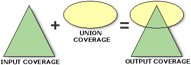
Computes the geometric intersection of two polygon coverages. All polygons from both coverages will be split at their intersections and preserved in the output coverage.
Illustration

Usage
The input coverage and the union coverage must have polygon topology.
Region subclasses in either the input or union coverage are maintained in the output coverage. Subclasses with identical names and attribute schemas are appended.
Label points are generated in each output coverage polygon. The new polygon User-IDs are set equal to the polygon internal number minus one.
The input coverage, union coverage, and output coverage must have different names, even when in different workspaces.
Existing input coverage annotation is copied to the output coverage by UNION.
Route systems in the input coverage will be maintained in the output coverage. However, UNION on routes and sections themselves is not permitted.
Region subclasses from both input coverage and union coverage are maintained. If the same subclass exists in both coverages, the subclass contents are appended. If the same subclass exists in both coverages but the item definitions are different, a message is given and the subclass is not propagated.
The coordinate precision of the output coverage is determined by the Precision for Derived Coverages environment.
Projection files will be compared for similarity using the level of comparison specified in the Compare Projections environment.
On single-precision coverages, UNION calculates a minimum tolerance based on the mathematical precision of the coverage (based on the width of the BND and the number of decimal places). If the calculated minimum tolerance is greater than the fuzzy tolerance entered, the calculated minimum tolerance is used.
The output coverage inherits the items from the point attribute table, tics, and the projection file data model contents from the input coverage.
When the input coverage contains linear data belonging to different planar graphs, the data will be maintained in the output coverage. For example, with coincident or colinear arcs, such as arcs representing utility cables at different levels or a road following a stream, the coincident and colinear line segments will be preserved. However, additional vertices may be inserted. In the case of intersecting arcs, such as a road passing over a stream, nodes will not be inserted at the apparent intersection.
Syntax
Union(in_cover, union_cover, out_cover, {fuzzy_tolerance}, {join_attributes})| Parameter | Explanation | Data Type |
in_cover | The coverage whose polygons will be combined with the union coverage. | Coverage |
union_cover | The union coverage whose polygons will be combined with the input coverage. | Coverage |
out_cover | The output coverage that will be created containing the results of the operation. | Coverage |
fuzzy_tolerance (Optional) | The minimum distance between coordinates in the output coverage. By default, the minimum fuzzy tolerance value from the input and union coverages is used. Learn more about how the default fuzzy tolerance is calculated | Double |
join_attributes (Optional) | Specifies whether all items in both the input and the union coverage will be joined to the output coverage feature attribute table.
| Boolean |
Code sample
Union example (stand-alone script)
The following stand-alone script demonstrates how to union two coverages.
# Name: Union_Example.py
# Description: Unions two coverages
# Requirements: ArcInfo Workstation

# Import system modules
import arcpy
from arcpy import env

# Set environment settings
env.workspace = "C:/data"

# Set local variables
inCover = "tong_azone"
unionCover = "tong_flood2"
outCover = "C:/output/studyarea"
joinAttributes = "NO_JOIN"

# Execute Union
arcpy.Union_arc(inCover, unionCover, outCover, "", joinAttributes)
Environments
Licensing information
- Basic: No
- Standard: No
- Advanced: Requires ArcInfo Workstation installed