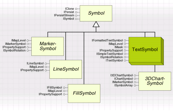
A symbol is a class that can draw things, such as points, lines, and areas, to a display. The Display object model contains a range of MarkerSymbols, LineSymbols, and FillSymbols, which can be used in conjunction with graphic elements or renderers to draw features, graphics, map surrounds, and so on. These can be combined into multilayer symbols to achieve a more complex display.
There are a number of different symbols available in ArcObjects, which are used to draw points, lines, areas, and text.
The TextSymbol can be used to draw text to the screen and is commonly used in labelling, annotation, and graphic elements. The more specialized 3DChartSymbols are used in conjunction with the ChartRenderer.

Is a custom symbol the right solution?
If none of the standard symbols can draw your features or graphics the way you require, you may find it useful to implement your own custom symbol. Custom symbols can be applied to any graphic element or feature, they can take part in other multilayer symbols and renderers, they can be edited by users like other symbols, and they can be saved and retrieved as StyleGalleryItems.
Multiple symbols of a similar type can be combined into a multilayer symbol.
If your drawing requirements are not met by these symbols, try implementing a custom symbol.
Before you go ahead and create a new type of symbol, you might like to review your alternatives to check that a custom symbol is your most appropriate action.
The clever combination and manipulation of the existing symbols can result in a great range of display options. CharacterMarkerSymbols, CartographicLineSymbols, and PictureFillSymbols in particular are flexible, and when you combine effects in a multilayer marker, line, or fill symbol, a wide range of effects can be achieved.
A good knowledge of the available options in ArcMap will help you decide, but you should also review the Display object modelit may be able to manipulate the existing symbols programmatically in a way that you cannot achieve using the ArcMap user interface.
Before implementing a custom symbol, check that you cannot get the effect you require through manipulation of the existing symbols.
A custom symbol is a relatively low-level solution; for example, it may exist without the presence of an MxDocument. It should never rely on the attributes of a particular feature—if required, you should consider a custom renderer instead. Also, a symbol does not generally change the location of an item—projections or the transformation of your data may be more appropriate here.
As you have programmatic access to the ScreenDisplay, you will find it is possible to draw items directly to the display without using a symbol, feature, or element. This type of solution may be appropriate to temporarily highlight the result of an operation, for example in the way that a feature is 'flashed' on the display when you select that feature in the Identify dialog box.
In general, drawing directly to the display may not be suitable. If your drawings need to be persisted with the document or after refreshing the view or if user interaction with the shape is required such as selection and editing, direct drawing may not be suitable.
Using custom symbols
Once you have decided on a custom symbol, you need to consider your implementation detail—show you can achieve the drawing effects you require.
When planning and testing your symbol, consider issues such as drawing efficiency and platform function support. Make sure you are familiar with the API you are using and surrounding issues. Consider your drawing efficiency—users may find it particularly frustrating waiting for drawing to complete on complex maps. Also consider platform support for GDI functions—your symbol may be drawn to a screen, exported to a file, or output to any type of printer.
Symbols may be drawn to many different types of devices—output files, printers, and screens. Ensure your drawing methods are suitable for these devices.
The Windows GDI is a mature platform for developers, and you should be able to find much information in the references in the bibliography and MSDN for further reading on this extensive topic.
Similarly, for those choosing to use alternative methods of drawing, efficiency and platform support should be considered, in addition to any issues specific to the method you are using.
Examples in this section
In the following sections you will see a custom MarkerSymbol, the simplest type of symbol. Many issues of designing and implementing a custom symbol are common to implementing a marker, line, fill, text, or chart symbol and are discussed in this example. In addition, there follows an example of a line symbol, which demonstrates not only a different type of symbol, but a different approach to drawing the symbol itself.
This section demonstrates how to create a custom symbol to draw points and lines.
See Also:
Logo Marker Symbol ExampleVertex Line Symbol Example
Creating other types of custom symbol
