To identify whether buildings cause unacceptable interference to facilities, an international standard has been created to describe the parameters that are used to construct imaginary surfaces around these facilities. The Communication Navigational Surveillance Surfaces tool allows users to create these surfaces in accordance with ICAO EUR DOC 015.
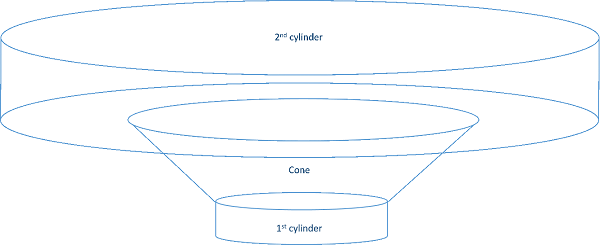
The following image is a depiction of surfaces created for omnidirectional facilities:

The following table reflects omnidirectional facilities:
Omnidirectional facilities
| Specification | Classification | First cylinder radius | Cone radius | Cone angle | Second cylinder radius | Second cylinder height |
|---|---|---|---|---|---|---|
Communication | VHF Communication Tx |  |  |  | ||
Communication | VHF Communication Tx |  |  |  | ||
Navigational | DME N |  |  |  | ||
Navigational | CVOR |  |  |  (Noneditable) |  |  |
Navigational | DVOR |  |  |  (Noneditable) |  |  |
Navigational | Direction Finder |  |  |  (Noneditable) |  |  |
Navigational | Markers |  |  |  | ||
Navigational | NDB |  |  |  | ||
Navigational | GBAS Ground Reference Receiver |  |  |  | ||
Navigational | GBAS VDB Station |  |  |  | ||
Navigational | VDB Station |  |  |  | ||
Surveillance | PSR |  |  |  | ||
Surveillance | SSR |  |  |  |
Navigation directional facilities
The following are the navigation directional facilities:
- ILS LLZ (medium aperture single frequency)
- ILS LLZ (medium aperture dual frequency)
- ILS GP M–Type (dual frequency)
- MLS AZ
- MLS EL
- DME (directional antennas)
All navigation directional facilities have the following parameters:
- a—Distance of the surface extending parallel from the antenna along the centerline of the directional fan.
- b—Distance of the surface extending parallel from the antenna, opposite along the directional fan, along the centerline of the directional fan.
- h—Height of the directionally sloped plane that describes the minimum height of interference.
- D—Distance of plane extending from the antenna perpendicular to the centerline of the directional fan. Height is determined by value of a.
- H—Height of the surface that extends from the bottom of the antenna up to the specified value that connects to the directional fan.
- L—Distance from the center of the antenna, perpendicular to the centerline of the directional fan, to the connection point of the sloped directional fan.
- r—Distance from the base of the antenna; describes the overall length of the directional fan.
- Phi—Represents the angle of the directional fan starting at the distance of D.
For a visual depiction of these measurements, refer to the ICAO EUR DOC 015 document.
Creating CNS surfaces for omnidirectional facilities
The workflow for creating the CNS surface for omnidirectional facilities is as follows:
- Démarrez ArcMap.
- On the main menu, click Customize > Toolbars > Aviation Airports.
-
Click the Communication Navigational Surveillance Surfaces button
 on the Aviation Airports toolbar.
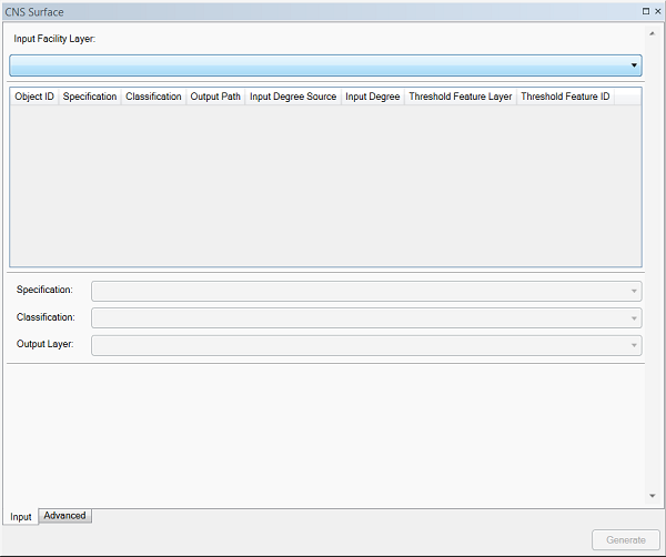
The CNS Surface dialog box appears.

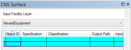
- On the Input tab, click the Input Facility Layer drop-down arrow and choose a layer.
This can be any point layer in the Table Of Contents window.
- Select the features in ArcMap for which you want to generate a surface.
- Highlight the record or records in the CNS Surface tool grid.

- Click the Specification drop-down arrow and choose from the following:
- Communication
- Navigational
- Surveillance
- Click the Classification drop-down arrow and choose a classification.
This value changes depending on the specification chosen.
- Click the Output Path drop-down arrow to define the path.
This is the layer in the Table Of Contents window that the output will be appended to.
- If necessary, click the Advanced tab.
The values listed are the default values as set per the specification chosen. These values are all editable except the cone angle, which is derived from the values from the second cylinder radius and the second cylinder height.
- Click Generate.
Creating CNS surfaces for directional facilities
The workflow for creating CNS surfaces for directional facilities differs from the workflow for omnidirectional surfaces. Directional surfaces require extra parameters to define the direction of the surface and the distance that it is based on from the facility.
- Démarrez ArcMap.
- On the main menu, click Customize > Toolbars > Aviation Airports.
-
Click the Communication Navigational Surveillance Surfaces button
 on the Aviation Airports toolbar.
- On the Input tab, click the Input Facility Layer drop-down arrow and choose a layer.
This can be any point layer in the Table Of Contents window.
- Select the features in ArcMap for which you want to generate a surface.
- Highlight the record or records in the CNS Surface tool grid.

- Click the Specification drop-down arrow and choose Navigational.
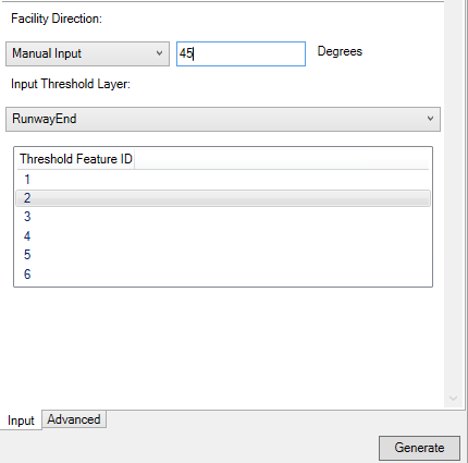
- Click the Facility Direction drop-down arrow and choose from the following:
- Input Layer
- Manual Input
- Type an appropriate value in the Degrees text box.
- Click the Input Threshold Layer drop-down arrow and choose a layer.
- Choose a row from the grid.

- If necessary, click the Advanced tab.
The values listed are the default values as set per the specification chosen. These values are noneditable.
- Click Generate.