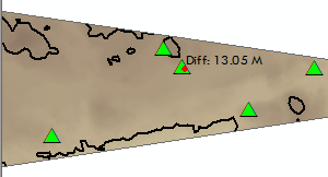
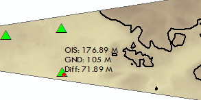
When you are trying to visualize the way a feature relates to an obstruction identification surface (OIS), it can be useful to digitize the features on a map on the fly and see the elevation difference between the terrain and the feature you have drawn. The Evaluate Obstacle tool allows you to view the elevation difference between the point and the ground elevation, as well as its distance from the runway centerline.
For example, suppose you are going to perform construction work on a building. You need to ensure that the height of the crane is not going to interfere with the minimum elevation for an aircraft that may be landing. With the Evaluate Obstacle tool, you can specify the height and width of the obstacle and view its distance above ground in relation to another feature. The location of the obstacle can be defined by manually entering coordinates or by clicking locations in the map; the method will vary based on whether you know the exact coordinates for the obstacle's location.

By default, you can see the elevation difference, but you can also choose to see the obstruction identification surface and ground elevations as well.

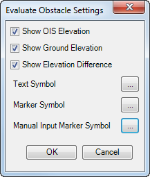
As needed, you can change the text symbol as well as the symbols for markers based on coordinates or locations clicked on the map.
To analyze obstruction features with this tool, the following must be in the map:
- OIS Surface—An OIS Surface feature class, which must be multipatch
- Runway—Runway centerline features
- Elevation Raster—A DEM with the elevation information
- Start ArcMap.
-
Open a map and ensure that it has the following:
- A multipatch feature class for the OIS surface
- The runway centerline feature class
- A DEM for the elevation information
- On the main menu, click Customize > Toolbars > Aviation Airports.
- Click the Evaluate Obstacle button
 on the Aviation Airports toolbar.
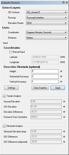
The Evaluate Obstacle dialog box appears. The OIS Surface, Runway, and Elevation Raster parameters are automatically populated based on what is in your map.

- To change the coordinates, click the Coordinates drop-down arrow in the Units area.
The default is Degrees Minutes Seconds. You can also choose Decimal Degrees.
- To change the units for distance, click the Distance drop-down arrow in the Units area.
The default is Meters. You can also choose Feet.
- Define the obstacle information based on coordinates or manually define the height and accuracy.
To define the obstacle based on coordinates
Check the Manual Input check box and type the coordinates in the Latitude and Longitude text boxes. Click Apply.
To define the obstacle based on the height and accuracy
Type the height of the obstacle in the Height text box, a horizontal buffer amount in the Horizontal Accuracy text box, and a vertical buffer amount in the Vertical Accuracy text box. Click Apply.
- Optionally change the settings for the information shown by the Evaluate Obstacle tool.
- Click Settings on the Evaluate Obstacle dialog box.
The Evaluate Obstacle Settings dialog box appears.

- Check the Show OIS Elevation check box to display the elevation of the OIS when you create a point.
- Check the Show Ground Elevation check box to display the ground elevation when you create a point.
- Change the font used to display the elevation figures by clicking the ellipsis button (...) next to Text Symbol.
- Change the marker symbol by clicking the ellipsis button (...) next to Marker Symbol.
This is the marker symbol used when you define an obstacle by clicking in the map.
- Change the marker symbol for manually input features by clicking the ellipsis button (...) next to Manual Input Marker Symbol.
This is the marker symbol used when you define an obstacle using coordinates.
- Cliquez sur OK.
- Click Settings on the Evaluate Obstacle dialog box.
- Click a point in the map.
The elevation difference for the point appears. If other measurements are selected, the ground and OIS elevations also appear next to the point.