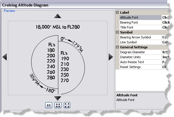
Before a cruising altitude diagram is added to an aeronautical chart, its appearance can be modified to meet product specification or organizational standards. This includes the size of the diagram, the fonts for the title, values, and bearings, and the symbols.
The following elements can be customized on the cruising altitude diagram:
- Altitude Font—The font used for the altitude values on the diagram
- Bearing Font—The font used for the bearing values for each part of the diagram
- Title Font—The font used for the diagram title, which appears above the element
- Bearing Arrow Symbol—The symbol used for the arrow that leads from the starting bearing to the ending bearing for a part of the diagram
- Line Symbol—The symbol used for the outline of the circle sections on the diagram
- Diagram Diameter—The diameter of the cruising altitude diagram in page units
- Diameter Units—The page units used to determine the diameter of the cruising altitude diagram
You can also indicate whether the text automatically resizes to fit in the diagram and reset the diagram to use default settings.
- Start ArcMap.
-
On the main menu, click
Customize > Production > Production Properties.
The Production Properties dialog box appears.
- Click Aviation Properties in the list on the left side of the Production Properties dialog box.
-
Click the cell next to Cruising Altitude Diagram and click the ellipsis (...) that appears.
The Cruising Altitude Diagram dialog box appears.

- To modify the labels on the diagram, click the cell next to Altitude Font, Bearing Font, or Title Font, and do the following:
- Click the cell next to the label you want to modify and click the ellipsis (...) that appears.
The Editor dialog box appears.
- Modify the label properties as needed.
Properties that can be modified include the font size, style, offset, angle, alignment, position, and masking.
- [OK] をクリックします。
The Cruising Altitude Diagram dialog box appears.
- Click the cell next to the label you want to modify and click the ellipsis (...) that appears.
- To modify the bearing arrows, click the cell next to Bearing Arrow Symbol, click the ellipsis (...) that appears, and modify the line and arrowhead symbols.
- To modify the line symbol that is the outline for the entire cruising altitude diagram, click the cell next to Line Symbol, click the ellipsis (...) that appears, and modify the color, thickness, and other properties of the circle sections on the diagram.
- To change the diameter of the cruising altitude diagram, click the cell next to Diagram Diameter and type a new value.
- To change the units of measure used for the diagram diameter, click the cell next to Diameter Units; then click the drop-down arrow that appears and choose an option.
- Millimeters—The cruising altitude diagram's diameter is displayed on the page in millimeters.
- Centimeters—The cruising altitude diagram is displayed on the page in centimeters.
- Inches—The cruising altitude diagram is displayed on the page in inches. This is the default.
- Points—The cruising altitude diagram is displayed on the page in points.
- To automatically resize the text inside the cruising altitude diagram, click the cell next to Auto Resize Text, click the drop-down arrow that appears, and click True.
The default value is False. When this is set to True, the Auto Resize Text check box is automatically checked on the Cruising Altitude Diagram dialog box when you add a new cruising altitude diagram.
- To reset the display settings for the cruising altitude diagram, click the cell next to Reset Settings, click the drop-down arrow that appears, and click True.
The cruising altitude diagram is reset to its default settings.
- [OK] をクリックします。