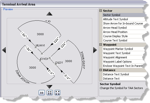
The Terminal Arrival Area (TAA) element appears in the plan view of an instrument approach procedure (IAP) and provides safe altitude and distance information. TAAs are found only on RNAV approaches. The element contains three parts that reflect the straight-in, right-base, and left-base areas for the approach. Each part can contain one or more designated points, an altitude label, and designated point identification labels.
The default style of new TAA elements is determined by the settings on the Terminal Arrival Area dialog box. Changing the settings does not alter existing TAA elements. Existing TAA elements can be updated by clicking the Terminal Arrival Area tool, which will regenerate the element based on updates to the data and/or settings.
You can preview changes to any settings on the Terminal Arrival Area dialog box, which allows you to see how the element is going to look on the chart layout before they are applied. The settings are divided into groups based on the part of the element they affect. The Sector group contains properties that affect the appearance of the different parts that comprise the TAA. The Waypoint group contains properties that affect the waypoint symbols and text. The Distance group contains properties that affect the appearance of the distance text outside of the different parts of the TAA.
- Запустите ArcMap.
- On the main menu, click Customize > Production > Production Properties.
The Production Properties dialog box appears.
- Click Aviation Properties in the list on the left side of the Production Properties dialog box.
-
Click the cell next to Terminal Arrival Area and click the ellipsis (...) that appears.
The Terminal Arrival Area dialog box appears.

- Click the cell next to Sector Symbol, click the ellipsis (...) that appears, then modify the symbol for the sector outline and fill.
- Click the cell next to Altitude Text Symbol, click the ellipsis (...) that appears, then modify the properties of the altitude text.
- Click the cell next to Show Arrow for In-bound Course, click the drop-down arrow that appears, and choose an option for displaying the arrows on the sectors.
If you choose False, the directional arrows do not appear for the inbound course. If you choose True, the arrows are displayed for the inbound courses.
- Click the cell next to Arrow Head Symbol, click the ellipsis (...) that appears, then modify the properties for the arrowhead symbol on the sector.
- Click the cell next to Arrow Head Position, click the drop-down arrow that appears, and choose an option.
- End Of line—The arrowhead appears at the end of the line, next to the waypoint.
- Middle Of Line—The arrowhead appears towards the middle of the line.
- Click the cell next to Course Display Style, click the drop-down arrow that appears, and choose an option:
- Show only magnetic value—Only the magnetic value is displayed on each sector.
- Show only grid value—Only the grid value is displayed on each sector, with a G appended to the bearing value.
- Show magnetic and grid value—Both the magnetic and grid values are displayed on each sector, with a G and M appended to the grid and magnetic values, respectively.
- Do not display course value—Neither the magnetic or grid values are displayed.
- Click the cell next to Course Text Symbol, click the ellipsis (...) that appears, and modify the properties of the course text.
- Click the cell next to Waypoint Marker Symbol, click the ellipsis (...) that appears, and modify the properties of the waypoint marker.
- Click the cell next to Waypoint Text Symbol, click the ellipsis (...) that appears, and modify the properties of the waypoint text.
- Click the cell next to Waypoint Alignment, click the drop-down arrow that appears, and choose an option.
- Align to Page—The waypoints are aligned with the page.
- Align to Inbound Course—The waypoints are aligned with the inbound course.
- Click the cell next to Waypoint Label Options, click the drop-down arrow, and choose an option for labeling waypoints on each sector.
- Label Only Predicated Waypoint—Only predicated waypoints are labeled.
- Label All Waypoints—All waypoints are labeled.
- Click the cell next to Enclose Waypoint Text In Parenthesis, click the drop-down arrow that appears, and click True or False.
This setting determines whether the waypoint text is enclosed in parentheses.
- Click the cell next to Distance Text Symbol, click the ellipsis (...) that appears, and modify the properties of the text that appears outside of the sectors.
- Click the cell next to Distance Text and type the text you want to appear between the distance value and the waypoint label.
Examples of the text that can appear include FROM and TO.
- Click the cell next to Show NoPT, click the drop-down arrow that appears, then choose True or False.
If the value is True, (NoPT) is appended to the distance text for the sector. If the value is False, no text is appended to the distance text.
- Click OK.
The Production Procedures dialog box appears.
- Нажмите ОК.