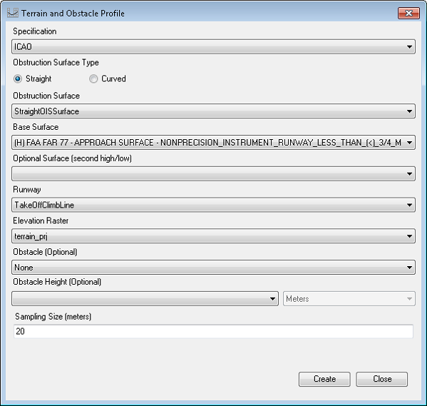
The terrain and obstacle profile element allows you to quickly visualize where obstacles and terrain protrude through an obstacle identification surface. The element provides an overview of the elevation of the obstacles and terrain, in meters, that impact the approach surfaces on either end of the runway. It also provides elevation changes in the runway.
The terrain and obstacle profile requires the following information:
- Specification name—This tool can be run using the FAA or ICAO specifications.
- Obstruction Surface Type—Option for selecting the OIS surface.
- Obstruction surface—The multipatch feature class that contains the obstruction identification surfaces. This feature class is required to have both DESCRIP and RWYDESG fields.
- Base Surface—The base surface being analyzed for obstructions and terrain. This description is used to provide the name of the surface.
- Path—The feature class that contains the flight path.
- Runway—The feature class that contains the runway centerline features. This feature class is required to have either a DESIGNATOR_TXT or RWYDESG field.
- Elevation raster—The raster containing the elevation data for the runway centerline.
- Sampling size—The size of the sample, in meters. The default is 20.
You can optionally specify the following:
- Obstacle—The feature class with the obstacle features.
- Obstacle height—The fields with the obstacle heights. This is from the obstacle feature class.
The element is placed at the bottom of the chart layout.
- 启动 ArcMap。
- Open a chart with obstruction, runway, and elevation information.
- Display the map in layout view.
- On the main menu, click Customize > Toolbars > Aviation Airports.
- Click the Terrain and Obstacle Profile button
 on the Aviation Airports toolbar.
The Terrain and Obstacle Profile dialog box appears.

- Click the Specification drop-down arrow and choose the specification for which to create the terrain and obstacle profile element.
You can choose ICAO or FAA. With the FAA specification, the profile extends the runway feature in line with the sampling size and collects the height at that point along the centerline. The ICAO specification extends the runway feature in line with the sampling size, creating a line perpendicular to the centerline and up to the edges of the obstruction surface, using the highest point along the perpendicular.
- For Obstruction Surface Type, choose one of the following depending upon the obstruction identification surface (OIS):
To generate a profile for a straight OIS surface
Click the Straight radio button and continue with steps 8 through 17.
To generate a profile for a curved OIS surface
- Click the Curved radio button and continue with steps 8 and 9.
- Click the Path drop-down arrrow and choose the layer containing the flight path.
- Follow steps 11 through 17 for the remaining parameters.
- Click the Obstruction Surface drop-down arrow and choose the layer containing the obstruction identification surface (OIS) features.
This layer must be currently loaded in the table of contents.
- Click the Base Surface drop-down arrow and choose the name of the obstruction surface for which to generate the terrain and obstacle profile.
This list is populated with the descriptions of the surfaces in the obstruction surface layer. It may display more than one surface from the obstruction surface layer, but you can only choose one. The chosen surface will set the vertical and horizontal extents of the generated profile.
- Click the Optional Surface (second high/low) drop-down arrow and choose the name of the secondary obstruction surface for which the terrain and obstacle profile will be generated. For example, the base surface would be as shown in the image in step 5, and the optional surface (second high/low) could be utility_runway_visual_approach.
- Click the Runway drop-down arrow and choose the feature class containing the runway centerline features.
This layer must be currently loaded in the table of contents.
- Click the Elevation Raster drop-down arrow and choose the raster that has the elevation information for the runway.
This layer must be currently loaded in the table of contents.
- Click the Obstacle (Optional) drop-down arrow and choose the feature class with the obstacle features.
This layer must be currently loaded in the table of contents.
- Click the Obstacle Height (Optional) drop-down arrow and choose the field in the obstacle feature class that contains the height values.
In addition to fields on the feature class, you can also choose to use the Z Value (AGL) or Z Value (AMSL) field, each of which contains the z-values stored on the obstacle feature.
- Optionally click the units drop-down arrow next to Obstacle Height (Optional), and change the units from Meters to something else.
- Optionally type a new value in the Sampling Size (meters) text box.
This is the distance from the end of the runway that will be sampled for obstruction and terrain features. The default value is 20.
- Click Create.
The terrain and obstacle profile is added to the chart layout. It may need to be moved to the bottom of the chart.