The linear referencing system (LRS) extends the geodatabase to provide additional capabilities for linear referencing, including support for multiple linear referencing methods (LRMs), event location management, and a time-aware LRS.
-
Right-click the target geodatabase and click
New > Advanced Linear Referencing System.
- In ArcCatalog, the geodatabase is in the Catalog tree.
- In ArcMap, the geodatabase is in the Catalog window.
The Advanced Linear Reference System Setup wizard appears.
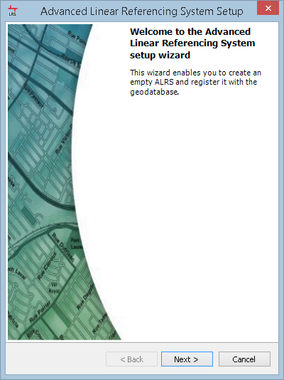
- 单击下一步。
- Name the new LRS and provide a brief description.
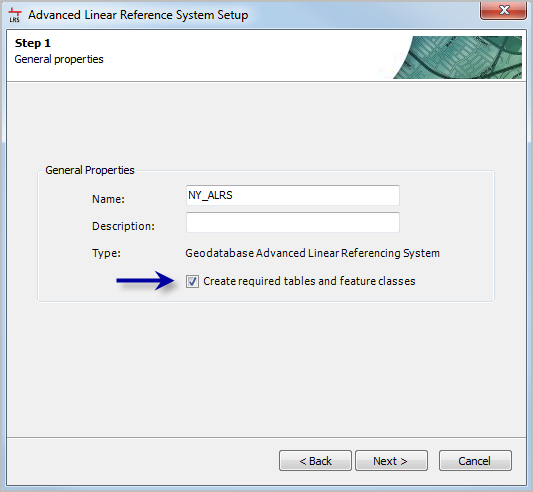
- Click Next.
The Step 2 of 7, Minimal schema dialog box appears.
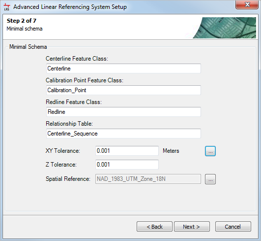
- Name the minimum schema items and select the tolerance and spatial reference.
- Choose the name for each minimum schema item.
- Select the x,y- and z-tolerance for the centerline, calibration point, and redline feature classes.
Enter the values by typing in the text boxes for X-Y Tolerance and Z Tolerance, or by selecting the tolerance values from an existing feature class, such as your source routes, by clicking the options button to the right of the text boxes.
- Select the spatial reference of your required tables and feature classes by clicking the options button next to the Spatial Reference field.
If you selected an existing feature class for your x,y and z-tolerance in the previous step, the spatial reference of that feature class is automatically selected for you. The spatial reference of your LRS should match the spatial reference of your source polyline route feature class.
- Click Next.
The Step 3 of 7, Schema dialog box appears.
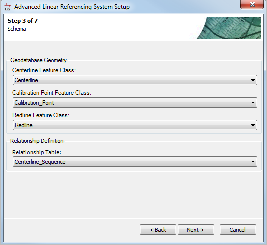
- Map the LRS schema to the proper data elements.
See LRS data model to learn about the data elements used in the LRS.
- Click Next.
The Step 4 of 7, Field Mapping dialog box appears.
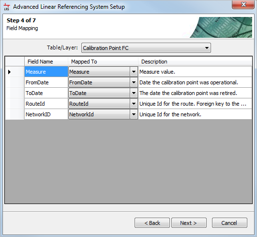
- Map fields to LRS data elements.
- Choose LRS data elements using the Table/Layer drop-down arrow.
- Map the LRS fields to the data element field names using the Mapped To drop-down arrow.
See LRS data model to learn more about the LRS data elements.
- Click Next.
The Step 5 of 7, Locks and Notifications dialog box appears.
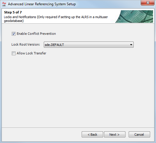
- If the LRS needs conflict prevention, check the Enable Conflict Prevention check box and choose the lock root version from the list of versions in the Lock Root Version drop-down list. If lock transfers between users will be allowed, check the Allow Lock Transfer check box. For more information on conflict prevention, see Conflict prevention.
This step is only available if the LRS is created in a multiuser geodatabase environment.
The Step 6 of 7, Elevation Dataset Configuration dialog box appears.
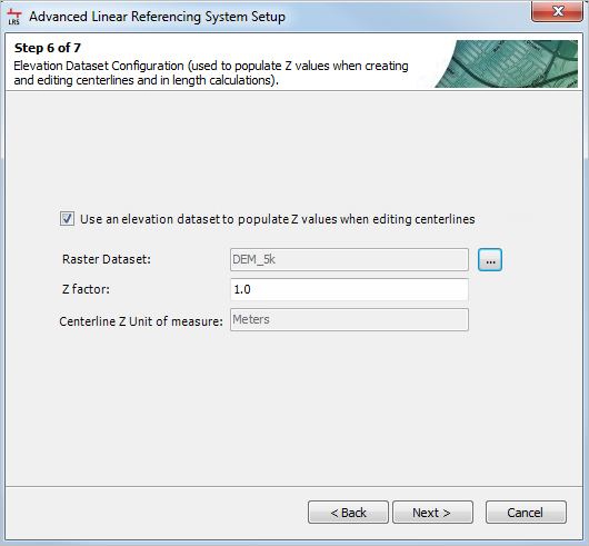
- If a digital terrain model, digital elevation model, or similar raster dataset is going to be used to calculate the z-values of centerlines when creating and editing them in Esri Roads and Highways, configure the Elevation Dataset Configuration. For more information about using z-values on centerlines, see Elevation data on routes.
This step is not required if an elevation model is not going to be used with your LRS.
- Check the Use an elevation dataset to populate Z values when editing centerlines check box if an elevation model is going to be used.
- Click the options button to the right of the Raster Dataset field to select your elevation model.
- Type the Z factor for the elevation model in the text box.
- The Centerline Z unit of measure field is populated automatically based on the spatial reference of the centerlines in the LRS.
- Click Next.
- Click Finish to finish creating the LRS and close the wizard.
The Question message appears, asking if you want to create a new network.
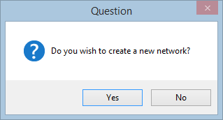
- Choose one of the options and close the LRS setup wizard.
- Click Yes to create a network.
- Click No to close the LRS setup wizard and return to ArcMap or ArcCatalog.