Available with Standard or Advanced license.
Click the links to see a detailed description of each parameter for the geometric effect.
| Input geometry | Output geometry | Geometric effect | Description | Example |
|---|---|---|---|---|
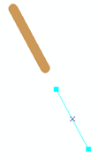
Point | Line | Creates a dynamic line of a specified length and angle originating from a point feature. |
| |
Polygon | Creates a dynamic polygon with a specified diameter around a point feature. |
| ||
Creates a dynamic polygon around a point feature with a specified number of edges. All edges are equal in length and all angles are equal. |
| |||
Line | Line | Dynamically adds representation control points to a line feature to dictate the placement of marker placement styles or geometric effects that use a template. | ||
Creates a dynamic line along a line feature with an arrow of a specified style and width. |
| |||
Creates a dynamic line that is shorter on one or both ends than a line feature. |
| |||
Creates dynamic multipart line geometry from a line feature based on a template. |
| |||
Creates a dynamic line that is extended from either the beginning or the end of the line feature at a specified deflection angle and length. |
| |||
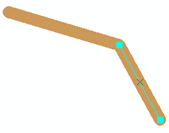
Creates a dynamic line with a jog of specified angle, position, and width in the line. |
| |||
Creates a dynamic line offset a specified distance in x and y; often used to mimic a drop shadow. |
| |||
Creates a dynamic line offset at a specified distance perpendicularly from a line feature. |
| |||
Creates a dynamic line that is offset from either the beginning or the end of the line feature at a specified distance. |
| |||
Flips the dynamic output of another geometric effect. | ||||
Creates a dynamic line rotated a specified angle from a line feature. |
| |||
Creates a dynamic line scaled by a specified factor from a line feature. Vertices are moved in relation to the center point of the feature envelope. Values greater than 1 move vertices away from the center point; values between 0 and 1 move vertices toward the center point; a 0 value creates a null dynamic line; values less than 0 draw an inverse dynamic line where the vertices have crossed to the other side of the center point. |
| |||
Creates a dynamic generalized line from a line feature using the Douglas-Peucker algorithm. |
| |||
Creates a dynamic Bézier curve from a line feature by setting a flat tolerance. |
| |||
Suppresses sections of line features between pairs of representation control points. |
| |||
Creates a dynamic line along a line feature with a repeating wave pattern that is either sinusoidal, square, triangular, or irregular. |
| |||
Polygon | Creates a dynamic polygon with a specified diameter around a line feature. |
| ||
Creates a dynamic polygon from the spatial extent of a line feature. |
| |||
Creates a dynamic polygon along a line feature, whose width varies by two specified amounts along its length, as defined by a percentage of the line feature's length. |
| |||
Polygon | Line | Creates a dynamic line that is shorter on one or both ends than the outline of a polygon feature. |
| |
Creates dynamic multipart line geometry from the outline of a polygon feature based on a template. |
| |||
Polygon |
Dynamically adds representation control points to the outline of a polygon feature to dictate the placement of marker placement styles or geometric effects that use a template. | |||
Creates a dynamic polygon with a specified distance around the outline of a polygon feature. |
| |||
Creates a dynamic polygon ring of a specified width in relation to the outline of a polygon feature. |
| |||
Creates a dynamic polygon from the spatial extent of a polygon feature. |
| |||
Creates a dynamic polygon whose outline is offset a specified distance in x and y from the outline of a polygon feature; often used to mimic a drop shadow. |
| |||
Creates a dynamic polygon whose outline is offset a specified distance from the outline of a polygon feature. |
| |||
Creates a dynamic polygon rotated a specified angle from a polygon feature. |
| |||
Creates a dynamic polygon scaled by a specified factor from a polygon feature. Vertices are moved in relation to the center point of the feature envelope. Values greater than 1 move vertices away from the center point; values between 0 and 1 move vertices toward the center point; a 0 value creates a null dynamic polygon; values less than 0 draw an inverse dynamic polygon where the vertices have crossed to the other side of the center point. |
| |||
Creates a dynamic generalized line from the outline of a polygon feature using the Douglas-Peucker algorithm. |
| |||
Creates a dynamic generalized line from the outline of a polygon feature by setting a flat tolerance. |
| |||
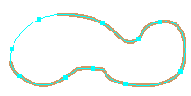
Creates a dynamic polygon outline along a polygon feature's outline with a repeating wave pattern that is either sinusoidal, square, triangular, or irregular. |
|
Parameter definitions
| Input geometry | Output geometry | Geometric effect | Definitions |
|---|---|---|---|
Point | Line | Radial from point | Angle: The orientation of the line from the marker. The default value is 0 (zero) degrees (due east). The angle is calculated in a counterclockwise manner. Length: The distance of the line from end to end. The default value is 5 pt. Adjusting this value changes the length of the dynamic line. |
Polygon | Buffer | Size: The distance from the edge of the marker. The default value is 1 pt. Specifying values greater than 1 creates a larger dynamic polygon around the marker. | |
Regular polygon | Radius: The distance from the center of the polygon. The default value is 2.5 pt. Specifying values greater than 1 creates a larger dynamic polygon around the marker. Edges: The number of sides for the polygon. The default number is 4. Specifying a value of 3 produces a triangle. Specifying a value less than 3 produces a circle. Angle: The amount of rotation for the polygon. The default value is 0 (zero) degrees. | ||
Line | Line | Add control points | Angle tolerance: The maximum amount of deflection from one segment to another at a vertex. The default value is 120 degrees. Angle values between 180 and 360 are interpreted the same as values between 0 and 180. Angle values of 180 and 360 are the same as 0 (zero). |
Arrow | Style: Indicates the type of arrow to be displayed. The choices are Open Ended, Block, and Crossed. Block displays an arrow with a closed end. Open Ended is a block arrow with an open end. Crossed indicates that a cross will be placed in the body of the arrow. The default value is Open Ended. Width: Indicates the distance between the lines that construct the body of the arrow. The default value is 20 pt. | ||
Cut | Begin cut: Indicates the distance from the beginning of a line that the display of the stroke starts. The beginning of a line is determined by the direction in which the line was digitized. The distance is applied along the line. The default value is 1 pt. End cut: Indicates the distance from the end of a line that the display of the stroke starts. The ending of a line is determined by the direction in which the line was digitized. The distance is applied along the line. The default value is 1 pt. Invert: Indicates the effect should be applied in the opposite manner. This displays the stroke symbol only at the ends of the line and leaves the rest of the line unsymbolized. The default value is unchecked. | ||
Dashes | Pattern: Indicates the distance for each dash and gap. There can be multiple dash and gap values to form a complex pattern. A dash is the symbolized part of the stroke, and a gap is the unsymbolized part of the stroke. When the length of the line does not support the display of the entire pattern, the pattern is compressed to fit. Using an odd number of values causes the pattern to double itself in overall length. The second half of the pattern is the reverse of the first half. Using a value of 0 (zero) is acceptable. These options allow more complex dash patterns to be created. The default values are 10 pt and 10 pt. Endings: The position of the dash along a line. The choices are No constraint, With half pattern, With full pattern, With half gap, With full gap, and Custom. Custom fits the pattern to the length of the feature by adjusting the gaps slightly. No constraint does not adjust the gaps at all, meaning that the pattern is unlikely to exactly fit the length of the feature. The default is With half pattern. Position: Indicates where the pattern should begin relative to the starting point of the geometry. It shifts the entire pattern along the line the specified distance. Negative numbers indicate a shift to the left, positive numbers a shift to the right. This property has an effect only if Endings is set to No constraint or Custom. When constructing a representation rule, this property is dynamically derived from the Step value and dynamically updates during rule construction or modification when the Endings property is updated. Offset at end: Indicates where the pattern should end relative to the ending point of the geometry. Negative numbers indicate a shift to the left, positive numbers a shift to the right. This property has an effect only if Endings is set to Custom. When constructing a representation rule, this parameter is dynamically derived from the Step value and dynamically updates during rule construction or modification when the Endings property is updated. | ||
Extension | Origin: The origin of the extension to add to the line. Deflection: The deflection angle used for the extension. Specify 0 for no deflection. Length: The length of the extension that is dynamically created. | ||
Jog | Length: The length of the segment that forms the jog in the line. Position: Location of the center of the jog, as a percentage measured from the start of the input geometry. Angle: The angle of the jog in the line, measured in degrees. | ||
Move | X Offset: The distance to move the symbol along the x-axis from the feature geometry. The default value is 1 pt. Y Offset: The distance to move the symbol along the y-axis from the feature geometry. The default value is -1 pt. | ||
Offset | Offset: The distance of the stroke perpendicular to the line's geometry. The default value is 1 pt. Method: Indicates the way the strokes are displayed at corners. The choices are Mitered, Bevelled, Rounded, and Square. Mitered matches the exact shape around a corner of the line. Bevelled follows the shortest straight path across a corner of the line. Rounded follows a path of equal distance around a corner of the line. Square follows a straight path across the corner of a line. The default value is Square. Option: Indicates the way strokes handle complex geometries. The choices are Fast and Accurate. Fast ignores complex geometries and applies a best fit to the stroke symbol. Accurate accommodates complex geometries and applies a true fit to the stroke symbol. The default value is Fast. Count: The number of times the stroke should be offset. The default value is 1. | ||
Offset tangent | Method: The origin of the tangent offset for the line. Offset: The distance the geometry is moved tangent. | ||
Reverse | Reverse: Indicates whether the dynamic output of a previous geometric effect is to be flipped or not. The default value is checked. | ||
Rotate | Angle: Indicates the amount of rotation for the stroke symbol. The default value is 15 degrees. | ||
Scale | X Factor: Indicates the amount of change in size of a stroke symbol in the x-axis. The value is expressed in terms of a ratio/percentage. The default value is 1.15, or 115 percent. Y Factor: Indicates the amount of change in size of a stroke symbol in the y-axis. The value is expressed in terms of a ratio/percentage. The default value is 1.15, or 115 percent. | ||
Simplify | Tolerance: Indicates the distance along a polygon outline to remove vertices from the stroke symbol. The default value is 10 pt. A value less than 10 maintains more of the original shape of the stroke. A value greater than 10 maintains less of the original shape of the stroke. | ||
Smooth | Flat tolerance: Indicates the distance along a line to include segments for a dynamic Bézier curve. The default value is 1 pt. A value greater than 1 considers fewer segments for a dynamic Bézier curve of the polygon outline. | ||
Suppress | Suppress: Indicates whether or not to suppress the sections of line features between two sets of control points. | ||
Wave | Period: Indicates the distance along a line to display the curve for the stroke symbol. The default value is 3 pt. Width: Indicates the distance perpendicular to a line to display the curve for the stroke symbol. The default value is 2 pt. Style: Indicates the shape of the curve to be displayed. The choices are Sinus, Square, Triangle, and Random. Sinus displays a sinusoidal curve or half moon shape. Square displays a three-sided rectangular-shaped curve. Triangle displays a two-sided triangular-shaped curve. Random displays a sine curve with random variation in the period and width of the curve. The default value is Sinus. Seed: Indicates the starting value for generating a random number. This random number is used by the Style type Random to determine which size a marker receives. The default value is 1. | ||
Polygon | Buffer | Size: The distance from the edge of the stroke. The default value is 1 pt. | |
Enclosing polygon | Method: Indicates the way in which the polygon geometry is generated around the stroke. The choices are Close path, Convex hull, and Rectangle box. Close path generates a polygon that connects both ends of the line to each other. Convex hull generates a polygon that approximates the shape of the line. Rectangle box generates a polygon equal to the spatial envelope of the line. The default value is Rectangle box. | ||
Tapered polygon | From width: Indicates the width at the start of the line to be used to generate a polygon. The default value is 0 pt (zero). To width: Indicates the width at the end of the line to be used to generate a polygon. The default value is 1 pt. Length: Indicates the distance along the line to be used to generate the polygon. The default value is 0 pt (zero). | ||
Polygon | Line | Cut | Begin cut: Indicates the distance from the closing point of a polygon that the display of the stroke starts . The distance is applied along the polygon outline. The default value is 1 pt. End cut: Indicates the distance from the closing point of a polygon that the display of the stroke starts . The distance is applied along the polygon outline. The default value is 1 pt. Invert: Indicates the effect should be applied in the opposite manner. This displays the stroke symbol only at the closing point of a polygon with the rest of the polygon outline unsymbolized. The default value is unchecked. |
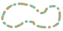
Dashes | Pattern: Indicates the distance for each dash and gap. There can be multiple dash and gap values to form a complex pattern. A dash is the symbolized part of the stroke, and a gap is the unsymbolized part of the stroke. When the length of the line does not support the display of the entire pattern, the pattern is compressed to fit. Using an odd number of values causes the pattern to double itself in overall length. The second half of the pattern is the reverse of the first half. Using a value of 0 (zero) is acceptable. These options allow more complex dash patterns to be created. The default values are 10 pt and 10 pt. Endings: The position of the dash along a polygon outline. The choices are No constraint, With half pattern, With full pattern, With half gap, With full gap, and Custom. Custom fits the pattern to the length of the feature by adjusting the gaps slightly. No constraint does not adjust the gaps at all, meaning that the pattern is unlikely to exactly fit the length of the feature. The default is With half pattern. Position: Indicates where the pattern should begin relative to the starting point of the geometry. It shifts the entire pattern along the line the specified distance. Negative numbers indicate a shift to the left, positive numbers a shift to the right. This property has an effect only if Endings is set to No constraint or Custom. When constructing a representation rule, this property is dynamically derived from the Step value and dynamically updates during rule construction or modification when the Endings property is updated. Offset at end: Indicates where the pattern should end relative to the ending point of the geometry. Negative numbers indicate a shift to the left, positive numbers a shift to the right. This property has an effect only if Endings is set to Custom. When constructing a representation rule, this parameter is dynamically derived from the Step value and dynamically updates during rule construction or modification when the Endings property is updated. | ||
Polygon | Add control points | Angle tolerance: The maximum amount of deflection from one segment to another at a vertex. The default value is 120 degrees. Angle values between 180 and 360 are interpreted the same as values between 0 and 180. Angle values of 180 and 360 are the same as 0 (zero). | |
Buffer | Size: The distance from the edge of the polygon outline. The default value is 1 pt. | ||
Donut | Width: Indicates the distance from the edge of the polygon that the fill symbol is to be displayed. The default value is 2 pt. Method: Indicates the way the strokes are displayed at convex corners of the polygon. The choices are Mitered, Bevelled, Rounded, and True buffer. Mitered matches the exact shape around a convex corner of the polygon. Bevelled follows the shortest straight path across a convex corner of the polygon. Rounded follows a path of equal distance around a convex corner of the polygon. True buffer uses the buffer algorithm to follow a path around convex corners. The default value is Mitered. Simple: Indicates whether or not complex geometries are dynamically simplified to generate a donut. It is checked by default. | ||
Enclosing polygon | Method: Indicates the way in which the polygon geometry is generated around the polygon feature. The choices are Close path, Convex hull, and Rectangle box. Close path generates a polygon that matches the geometry of the polygon feature. Convex hull generates a polygon with a minimum number of sides to surround the polygon feature. Rectangle box generates a polygon equal to the spatial envelope of the polygonal feature. The default value is Rectangle box. | ||
Move | X Offset: The distance to move the symbol along the x-axis from the feature geometry. The default value is 1 pt. Y Offset: The distance to move the symbol along the y-axis from the feature geometry. The default value is -1 pt. | ||
Offset | Offset: The distance of the polygon outline perpendicular to the polygon's geometry. The default value is 1 pt. Method: Indicates the way the fill is displayed at corners. The choices are Mitered, Bevelled, Rounded, and Square. Mitered matches the exact shape around a corner of the polygon. Bevelled follows the shortest straight path across a corner of the polygon. Rounded follows a path of equal distance around a corner of the polygon. Square follows a straight path across the corner of a polygon. The default value is Square. Option: Indicates the way the polygon outline handles complex geometries. The choices are Fast and Accurate. Fast ignores complex geometries and applies a best fit to the polygon outline. Accurate accommodates complex geometries and applies a true fit to the polygon outline. The default value is Fast. Count: The number of times the stroke should be offset. The default value is 1. | ||
Rotate | Angle: Indicates the amount of rotation for the fill symbol. The default value is 15 degrees. | ||
Scale | X Factor: Indicates the amount of change in size of a fill symbol in the x-axis. The value is expressed in terms of a ratio/percentage. The default value is 1.15, or 115 percent. Y Factor: Indicates the amount of change in size of a fill symbol in the y-axis. The value is expressed in terms of a ratio/percentage. The default value is 1.15, or 115 percent. | ||
Simplify | Tolerance: Indicates the distance along a polygon outline to remove vertices from the stroke symbol. The default value is 10 pt. A value of less than 10 maintains more of the original shape of the polygon outline. A value of greater than 10 maintains less of the original shape of the polygon outline. | ||
Smooth | Flat tolerance: Indicates the distance along a polygon outline to consider segments for a dynamic Bézier curve of the polygon outline. The default value is 1 pt. A value greater than 1 considers fewer segments for a dynamic Bézier curve of the polygon outline. | ||
Wave | Period: Indicates the distance along a polygon outline to display the curves for the fill symbol. The default value is 3 pt. Width: Indicates the distance perpendicular to a polygon outline to display the curves for the fill symbol. The default value is 2 pt. Style: Indicates the shape of the curves to be displayed along the polygon outline. The choices are Sinus, Square, Triangle, and Random. Sinus displays a sinusoidal curve or half moon shape. Square displays a three-sided rectangular shape. Triangle displays a two-sided triangular shape. Random displays a sine curve with random variation in the period and width of the outline, and the interior of the polygon remains fully symbolized. The default value is Sinus. Seed: Indicates the starting value for generating a random number. This random number is used by the Style type Random to determine which size a marker receives. The default value is 1. |


