Mit der Network Analyst-Lizenz verfügbar.
Voraussetzung:
- The Erweiterung "ArcGIS Network Analyst" must be installed and licensed, and the extension must be enabled before you can perform any network analysis and generate schematic diagrams based on network analysis results.
- Before generating diagrams from a network dataset, you must create a schematic diagram template in your schematic dataset and configure it to work with the Network Dataset builder.
- Learn more about configuring diagram templates with the Network Dataset builder
For generating schematic diagrams based on the Network Dataset builder, the easiest way is to start ArcMap and create or load a .mxd file that references the network dataset data from which you want the Network Dataset builder to operate.
Schematic diagrams can be generated from any network analysis layer containing a performed network analysis. You must use the tools and commands on the Network Analyst toolbar to set up and perform any route, closest facility, service area, or vehicle routing problem network analysis before being able to generate your schematic diagram on this network analysis result.
At any time, the generated diagrams can then be updated so their content is always in accord with any new network analysis result that is performed on the network.
The following section details the steps to generate a Network Dataset builder schematic diagram in ArcMap.
- Start ArcMap and load the .mxd file that contains the network dataset from which you want to generate schematic diagrams.
- Use the tools on the Network Analyst toolbar to set up and perform any route, closest facility, service area, or vehicle routing problem network analysis on this network dataset.
- Click the Generate New Schematic Diagram button
 on the Schematic toolbar.
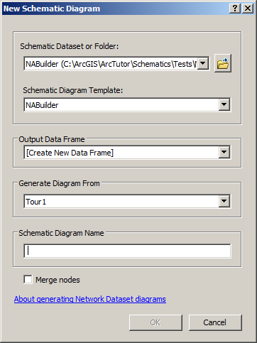
The New Schematic Diagram dialog box opens.

- Click the Schematic Dataset or Folder drop-down arrow and choose the schematic dataset or the schematic folder in the desired schematic dataset where the generated schematic diagram will be stored.
Learn more about the schematic datasets/folders suggested by default in this drop-down list
- Click the Schematic Diagram Template drop-down arrow and choose the schematic diagram template based on the Network Dataset builder that will be used to generate the schematic diagram.
All the predefined schematic diagram templates available from the currently selected schematic dataset specified in the Schematic Dataset or Folder drop-down list are itemized in this list.
- Keep the [Create New Data Frame] default value in the Output Data Frame drop-down list so the generated schematic diagram is automatically displayed in a new data frame, or select the data frame in which you want the generated schematic diagram to be added from that drop-down list.
- Click the Generate Diagram From drop-down arrow and choose the solved network analysis layer on which the schematic diagram will be based.
This drop-down list contains all the solved network analysis layers available in the table of contents on which the schematic diagram can be based.
- Type a name for the diagram that will be generated.
- Check the Merge nodes check box if you want network element junctions, which appear several times in the resultant network analysis, to be represented by a single schematic node in the generated schematic diagram. By default, this option is unchecked; that is, several schematic nodes are created in the generated schematic diagram to represent the same network element junction.
Edges that follow several times along the resultant network analysis are never merged even if this option is checked, but these schematic links are overlapping in the schematic diagram generated with the Merge nodes option.
- Click OK.
The schematic diagram is generated and displayed in the specified data frame. It is now referenced in the schematic database.