Available with Standard or Advanced license.
When you read the COGO descriptions for boundaries on a survey plan or other legal document, the directions and distances are measured on the surface of the earth. These are referred to as ground measurements. However, the directions and distances in your GIS data are based on the spatial data's coordinate system, or the grid measurements.
Ground and grid measurements are often different. You may set constants (the ground to grid correction) for directions and distances so that the software can correctly convert between the ground and grid measurements.
Why correct directions?
A surveyor may measure angles on the ground relative to any of several definitions of north: true north, magnetic north, grid north, or a locally defined north. However, directions in your spatial data are always relative to the coordinate system's grid north. Ground and grid directions must be rotated to convert one into the other.
The direction offset is an angle that is added to ground directions to rotate them to grid directions or that is subtracted from grid directions to rotate them into ground directions.
Why correct distances?
A surveyor measures distances on the ground relative to the local ground elevation. However, grid distances in your spatial data are always measured relative to the coordinate system's ellipsoid (to simplify matters, sea level).
For example, a 1,000-foot line surveyed at a high elevation must be scaled down to fit the earth's ellipsoid at sea level. So its grid distance is somewhat less than 1,000 feet:

The distance factor is a scale factor that is used to multiply ground distances to convert them to grid distances or to divide grid distances to convert them into ground distances.
Where is the correction specified?
The correction constants (Direction Offset for directions and Distance Factor for distances) are part of the ArcMap editing environment. You can set them on either the Units tab of the Editing Options dialog box or with the Ground to Grid Correction dialog box opened from the COGO toolbar.
When is the correction applied?
The ground to grid correction affects all direction and distance inputs that you make in the ArcMap editing environment, whether you are entering the bearing for a course in the Traverse window or constraining a vertex to a specific direction with the sketch construction tools. Your inputs are assumed to be in ground measurements; they are corrected to grid measurements and used to construct the feature geometry. Any command that writes the COGO descriptions you enter to COGO attribute fields will always write the uncorrected ground measurements.
Determining the correction
If you don't set a direction or distance correction, the geometry of newly constructed features will be rotated or scaled improperly relative to the coordinate system grid. There are several ways you can find the ground to grid corrections for a particular survey plan or legal document:
- Examine the survey plan or legal document for the corrections, which may be called the basis of bearing or convergence angle for directions and scale factor for distances. Look for statements such as "Bearings shown hereon are based on an assumed bearing of..."
- Consult government publications on state plane coordinate systems that describe the basis of bearing and scale factors at locations throughout the specific coordinate system.
- Use the Ground to Grid Correction dialog box launched from the COGO toolbar to calculate the corrections from existing features that also appear on your plan or document.
- Use the COGO Report command on the COGO toolbar to calculate averaged correction values from existing features.
You should set the correction, or at least check the current correction, before you start entering features from a new survey plan or legal document. However, you might not want to change the corrections in the middle of entering features from that same plan since you could introduce slight differences in the geometries you create.
Converting from ground to grid
When you use directions and distances to construct feature geometry, ArcMap assumes you are entering the values in ground-based measurements and uses the corrections to convert them to grid-based measurements before it constructs the geometry.
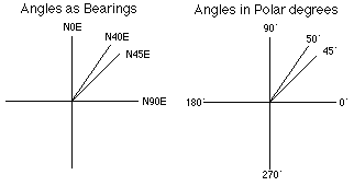
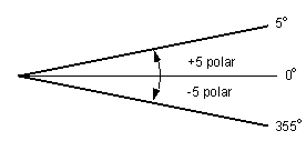
The direction offset is an angle that is added to the ground direction measurement to rotate it to match the grid direction. Positive angles rotate counterclockwise and negative angles rotate clockwise. This may seem backward (negative values typically rotate counterclockwise); however, it makes sense when you consider the direction you entered is converted to a polar direction before the direction offset is applied. In the polar system, you measure from the x-axis, and positive angles increase in a counterclockwise direction.
Here's an example. Suppose you set Direction Offset to -5°. If you enter a ground direction of N40°E, the resulting line feature will have a grid direction of N45°E, even though N40°E is written to the COGO Direction field. The steps below show how ArcMap applies the direction offset in this example:
- Convert N40°E to a polar direction: N40°E = 50°.

- Add the direction offset: 50° + (-5°) = 45°.

- Convert the polar direction back to quadrant bearing: 45° = N45°E.
The distance factor is used to multiply the ground distance to scale it to match the grid distance. For example, if Distance Factor is set to 0.95 and you enter a ground distance of 100 feet, the resulting line feature will have a grid distance of 95 feet (the shape length), even though 100 is written to the COGO Distance field.
Converting from grid to ground
When you measure a direction and distance in the map, you are working in grid measurements. If there is a ground to grid correction set, the direction, offset, and distance factors are applied to the grid measurements in reverse order to calculate the ground measurements. That is, the direction offset is subtracted from the grid direction, and the grid distance is divided by the distance factor.
The following editing commands apply the correction in reverse:
- The construction tools' constraints on direction and length
- The edit sketch segment direction and length reported in the ArcMap status bar
- The COGO Report command
- The Split Into COGO Lines command
- The Update COGO Attributes command
Using the Ground to Grid Correction dialog box
The Ground to Grid Correction dialog box allows you to enter the ground to grid correction in three ways, including typing in values and interactively changing the correction.
Typing the correction you read from a plan
The Ground to Grid Correction dialog box lets you type in the corrections, the same way as the Units tab of the Editing Options dialog box. Use this approach if the corrections are stated on your plan or you have used the COGO Report dialog box to calculate an average correction across the area in which you are working.
Entering the ground line and clicking the map for the grid line
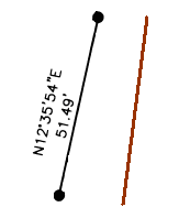
If you have an existing line in your dataset that you know the ground direction and distance for, you can use this approach to set the corrections. An example of how you can use this option is below. In the graphic below, the feature on the left describes a line on a survey plan; on the right is a feature representing that same boundary. You can use the Enter the ground line and click on the map for the grid line option. First, type the direction and distance, then click the ends of the line feature to set the correction.

Clicking the map for the ground and grid lines
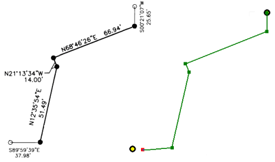
If you have points in your dataset that represent both the ground and grid lines, you can use this approach to set the corrections. An example of how you can use this option is below. The graphic on the left describes a traverse between two control points. On the right, the two control points have been added as point features into the dataset. Next, you can create an edit sketch without a ground to grid correction set that starts at the northern control point and ends near the southern control point. The difference between the control points and the edit sketch represents the ground to grid correction. Finally, you can use the Click the map for the ground and grid lines option. Click the two control points first, then click the ends of the edit sketch to set the correction.

If you only want to set the direction offset, use the Enter the ground line and click on the map for the grid line option and type a distance of 0.