Available with Standard or Advanced license.
A new parcel traverse is entered under on the Lines tab of the Parcel Details dialog box. The attributes of the new parcel are entered on the Properties tab. New parcels are created in plans. If you are not working with plans, use the <map> plan, which is the system default plan.
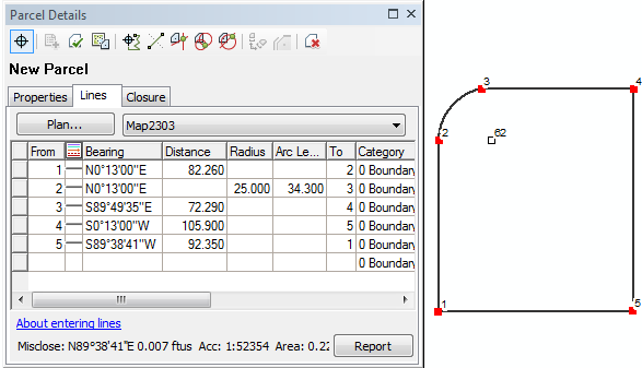
Create a new parcel traverse
To create a new parcel traverse, do one of the following:
- Click the New Parcel tool
 on the Parcel Editor toolbar.
 - Open the Plan Directory dialog box (Parcel Editor > Plan Directory), right-click a plan click New Parcel .
- Right-click a plan node on the Parcel Explorer window and click New Parcel.
Traverse dimensions are entered in the lines grid using the ENTER, LEFT ARROW and RIGHT ARROW keys. Once the to-point of the last leg of the traverse snaps or closes on to the from-point of the first leg of the parcel traverse, misclose information is displayed at the bottom of the Parcel Details dialog box. The to-point of the last traverse leg will automatically snap to the from-point of the traverse if the to-point lies within the tolerance you specified for point matching. To specify a tolerance for point matching, open the Parcel Editor Options dialog box (Parcel Editor > Options) and click the Tolerances tab.
Learn more about data entry in the parcel traverse grid
After entering the parcel traverse, click Keep And Join  to save and join the parcel to the parcel fabric layer or click Keep Changes
  to save the parcel as unjoined.
Create an unclosed parcel traverse
Unclosed parcels are used to represent features such road centerlines in the parcel fabric. An unclosed parcel does not rely on an internal traverse loop that closes onto its starting point. While unclosed parcels are comprised of line features, they are stored as parcels in the parcel fabric. Unclosed parcels behave like normal parcels in the parcel fabric in that they need to be connected to the rest of the parcel fabric network.
Use the parcel traverse tool to create unclosed parcels.
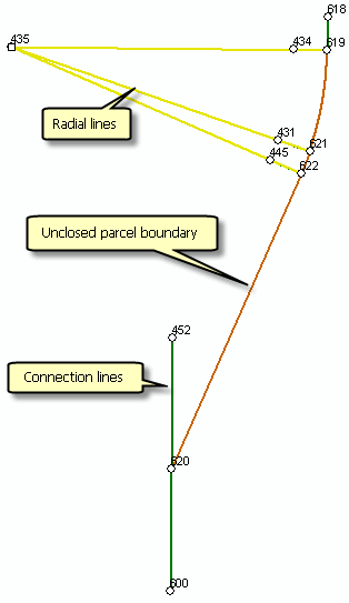
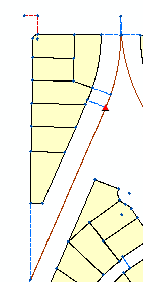
- In an edit session in ArcMap , use the Parcel Details dialog box to enter traverse lines just like you would for normal parcel.
The traverse lines do not close back onto the starting point.
- After you have finished entering your traverse lines, click the Properties tab, click the field next to Unclosed and choose True from the drop-down list.
If you are using the Local Government Information Model, make sure the Unclosed field is visible in the Parcel Details dialog box. Right-click the parcel layer in which you will create the unclosed parcel, click Properties and choose the Unclosed field under the Fields tab to make it visible.
- Click Keep Changes
 to save the parcel as unjoined or click Keep And Join
  to save and directly begin joining the parcel to the parcel fabric.
Append traverse lines from a cadastral XML file
When creating a new parcel, you can click Load Cadastral XML  on the Parcel Details dialog box to append a parcel traverse from a cadastral xml file into the Lines grid. The Load Cadastral XML command appends a single set of parcel traverse lines. Any populated line attributes saved with the cadastral xml file are also appended into corresponding attribute fields in the Lines grid.
A new parcel must be created first before you can click Load Cadastral XML  to load parcel traverse lines. Only traverse lines and their attributes are loaded into the Lines grid. The parcels plan, template and other attributes such as Accuracy are not loaded . This information must still be defined when you create the new parcel. Since the StatedArea, Rotation, Scale and MiscloseDistance attributes are derived from the parcel traverse, these attributes are populated when the traverse is loaded.
To load and join one or many complete parcels from a cadastral xml file, click Append File on the Parcel Editor menu.
Creating a new parcel traverse using internal angles
In some cases, parcel dimensions on a plan or record of survey are shown as angles and distances instead of bearings and distances. In this case, the parcel is entered using its internal angles.
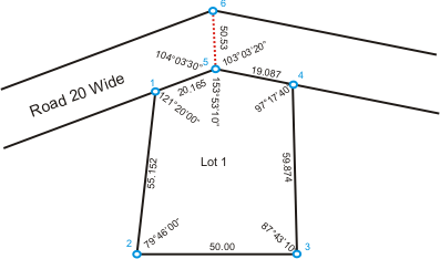
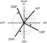
A parcel traverse using internal angles requires a Starting back-sight value. The starting backsight is the orientation angle, which is used as a reference for entering the first traverse leg. The starting backsight is based on a north azimuth angle type, and the default backsight is 180 degrees.
For example, if you traversed Lot 1 from the above graphic, you could use 90° as a starting backsight when entering the first traverse leg between points 1 and 2.
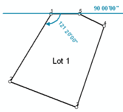
The remaining angles are oriented with respect to the previous line entered in the parcel traverse. When the parcel is joined to the parcel fabric, it is rotated and scaled accordingly.
To enter side shots or connection lines in an internal angle parcel traverse, the angle measured to the connection line needs to be referenced to an existing line in the parcel traverse. The to-point of the reference line is required as the ReferenceObject value in the parcel traverse grid. For example, when entering the connection line between points 5 and 6 for Lot 1 in the graphic above, the referencing backsight line can either be the line between 5 and 4 or the line between 5 and 1. The reference object would thus be either 4 or 1.
- Create a new plan to store parcels with internal angles.
On the Plan Properties dialog box, click the Record Format tab and set Direction or Angle Type to Internal Angle.
- In an edit session in ArcMap, open the Plan Directory dialog box (Parcel Editor > Plan Directory), right-click the plan created for internal angle parcels and click Create new parcel.
- Type in a starting backsight direction in the Starting back-sight text box under the Lines tab on the Parcel Details dialog box.
- Enter your first traverse leg. Your first traverse angle is oriented from your starting backsight.
- Enter your remaining traverse legs. Each traverse leg is oriented with respect to the previous traverse leg.
- To enter a side shot or connection line, type in the angle and distance of the connection line and type in the reference object of the connection line in the ReferenceObject field. The reference object is the to-point of any line that has the same from-point as the connection line. Angles going counterclockwise are entered as negative values, and angles going clockwise are entered as positive values.