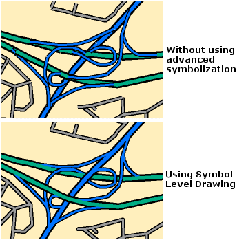
Many users often need to display road networks and want to represent their connectivity in term of overpasses, underpasses, bridges, and so forth. This would occur in any situation where road connectivity and navigation pathways need to be portrayed.
Learn more about configuring symbol level drawing

Here are the steps for a simple example:
- Symbolize your line features so that you have a different symbol for each combination of road types—for example, Interstate, State highways, Surface streets—and any desired multilayered symbols.
- Open the Symbol Levels dialog box for your feature layer or group layer and turn on symbol level drawing.
- Change the draw order of your symbols based on the order that you want your lines represented on the map. Symbols at the top of the list are drawn last.
- Set your Join and Merge settings.
In these categories, also define road elevation levels so that you can discern the drawing order for each. For example, if you have complicated interchanges, your list of levels might include Ground level (0), Ramp (1), Overpass (2), Second Overpass (3), and so on.
Generally, when symbolizing roads, you will want all road symbols to be joined to represent connected roads. However, only merge two symbols if you want them to appear to be connected on the map. For an overpass/underpass effect, specify no merge.