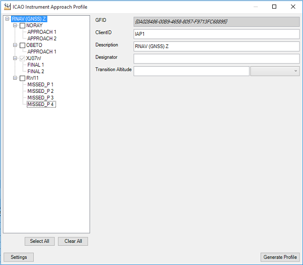
In an instrument approach chart, a profile view shows a transition into an airport. ArcGIS for Aviation provides a data driven tool that will allow you to easily create and modify this view for your terminal charts. New instrument approach profile views are created based on properties set on the ICAO Instrument Approach Profile dialog box. The properties that determine the default appearance and style of newly created instrument approach profile views are accessible through updating general settings. You can also define some appearance settings before creating a profile view.
The ICAO Instrument Approach Profile tool draws the final transition of the procedure, by default, unless any additional transitions are chosen from the tree view in the ICAO Instrument Approach Profiletool. For example APPROACH, MISSED_APPROACH, and so on.
Creating the ICAO profile view
- Start ArcMap.
- On the main menu, click Customize > Toolbars > Aviation Terminal Procedure.
-
Click the ICAO Instrument Approach Profile button
 on the Aviation Terminal Procedures toolbar.
The ICAO Instrument Approach Profile dialog box appears.

By default, all the procedures in the production database's TerminalProcedure table are listed.
- Approaches
- Final legs
- Missed approaches
- You can choose a singular approach or all approaches for the procedure.
- Click Generate Profile to generate the instrument approach profile view.
The profile view is created.
- Optionally click the ICAO Instrument Approach Profile button
 to return to the choices for editing or updating required and critical values.
 - Optionally click the Update Profile button to update the profile values that you have changed.
For example, if you changed Upper Altitude Value from 2000 to 3000. Any changes made to values are automatically saved to the database.
You need to regenerate the profile view if you made a change, such as adding a new Approach Transition.
Modifying general settings
You can modify general settings before or after creating a profile view to update the appearance of the instrument approach profile view and its basic elements by clicking the Settings button on the ICAO Instrument Approach Profile dialog box.
- Click the cell next to Units, click the drop-down arrow that appears, then choose another unit.
- Click the cell next to Width and type another value for the dimension width.
- Click the cell next to Height and type another value for the dimension height.
- Click the cell next to Frame Symbol, click the ellipsis button (...) that appears, then modify the frame symbol properties.
- Click the cell next to Reset Settings, click the ellipsis button (...) that appears, then click Yes to reset all the settings.
Modifying tray settings
You can modify tray settings to update the runway settings.
- Click the cell next to Tray Height, click the drop-down arrow that appears, then choose another height.
- Click the cell next to Tray Symbol, and type another value.
- Click the cell next to Runway Symbol, click the ellipsis button (...) that appears, then choose the symbol.
- Click the cell next to Runway Width and type another value.
- Click the cell next to Runway Height and type another value.
- Click the cell next to Runway Offset, and type another value.
- Click the cell next to Distance Text Symbol, click the ellipsis (...) that appears and modify the altitude text font properties.
Modifying procedure fix settings
You can modify these settings to update vertical line depiction in the instrument approach profile view.
- Click the cell next to Reference Fix Symbol, click the ellipsis button (...) that appears, then modify the line symbol properties.
- Click the cell next to Navaid Fix Symbol, click the ellipsis button (...) that appears, then modify the line symbol properties.
- Click the cell next to Marker Beacon Symbol, click the ellipsis (...) that appears, then choose the symbol.
- Click the cell next to Ident Text Symbol, click the ellipsis (...) that appears, modify the ident text font properties.
- Click the cell next to DME Distance Format, click the ellipsis (...) that appears, modify the distance label format properties.
Modifying procedure leg settings
You can modify these settings to update the properties of the procedure legs in the instrument approach profile view.
- Click the cell next to Procedure Leg Symbol, click the ellipsis button (...) that appears, then modify the procedure leg line symbol properties.
- Click the cell next to Missed Approach Leg Symbol, click the ellipsis button (...) that appears, then modify the missed approach leg line symbol properties.
- Click the cell next to Localizer Symbol, click the ellipsis button (...) that appears, then modify the localizer symbol properties.
- Click the cell next to Localizer Display Style, click the ellipsis button (...) that appears, then choose either Full Feather or Flat Top.
- Click the cell next to Final Approach Fix Symbol, click the ellipsis button (...) that appears, then modify the final approach symbol properties.
- Click the cell next to Visual Descent Point Symbol, click the ellipsis button (...) that appears, then modify the descent symbol properties.
- Click the cell next to Heading Arrow Symbol, click the ellipsis button (...) that appears, then modify the arrow symbol properties.
- Click the cell next to Heading Text Symbol, click the ellipsis button (...) that appears, then modify the heading text properties.
Modifying altitude settings
You can modify altitude settings to update the appearance of the altitude in the instrument approach profile view.
- Click the cell next to Altitude Font, click the ellipsis (...) that appears and modify the altitude text font properties.
- Click the cell next to Altitude Bar Symbol, click the ellipsis (...) that appears and modify the symbol properties.
- Click the cell next to Leader Line Symbol, click the ellipsis button (...) that appears, then modify the line properties.