Available with Production Mapping license.
The neatline component is made up of polyline features in the segments feature class. These lines follow the boundary of the source polygon, and any number of neatlines may be created.
Learn more about adding a new grid
The neatline is offset from the source feature (area of interest), and all segments that make up the neatline can have the same setting or be unique. You can set the offset from the source polygon using any numeric value along with any supported ArcGIS unit. You can define the neatline so the line segments have the following settings:
- All line segments have the same settings.
- Each line segment may have different settings—Each segment can have any number of child components, with settings that are different from each other. Any changes made to a segment do not affect the remaining segments.
If the grid is created for areas of interest that are non-rectangular (for example, trapezoid), angle ranges for grid segments can be assigned that match the area of interest segments by setting an origin value for the angle. The intervals of the ranges are determined by the number of segments in the neatline.
Creation of grids and graticules for areas of interest (AOI) that have more than four sides, or are non-rectangular, can be automated using the Grids and Graticules Designer. Such AOIs have sides that begin and end at specific angles within 360 degrees. Configuring a grid template XML with each segment having a minimum and maximum angle (angle range) set helps to determine the AOI side it matches. Angle ranges in grid segments are set at equal intervals and are mutually exclusive (that is, a range of one segment cannot overlap with a range of another segment). The interval is calculated by the number of segments in the grid, divided by 360 degrees. The angle range starts from a user-defined origin set in the neatline, and each segment is associated with the AOI based on the angle range.
In the following image, the thick red line shows the segment with an origin at 315 degrees. Therefore, if this is applied to a four-sided non-rectangular AOI, the angle range for the segment will be 315 to 45 degrees.

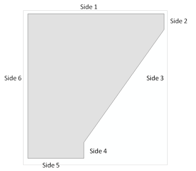
The area of interest shown below has six sides drawn at different angles that will match with the segment angles as shown above.

For a grid template with four segments and the origin at 315, the interval will be 90 degrees and the AOI sides and associated angle ranges will be:
- Side 1—315 to 45 degrees
- Sides 2 to 4—45 to 135 degrees
- Side 5—135 to 225 degrees
- Side 6—225 to 315 degrees
For a grid template with three segments and the origin at 315, the interval will be 120 degrees and AOI sides and associated angle ranges will be:
- Side 1—315 to 75 degrees
- Sides 2 to 5—75 to 195 degrees
- Side 6—195 to 315 degrees
Options are also available for the neatline densification:
- Source Area of Interest Coordinate System—The neatline and its associated segments have extra vertices added using the source area of interest (AOI) feature class's spatial reference. The result is a neatline with vertices that adjust more to project differences between the grid's primary coordinate system and the AOI's coordinate system. This option is useful if the AOI is stored using a cylindrical/rectangular spatial reference (that is, WGS84, UTM, and Mercator) and the grid's primary coordinate system is not (that is, conic, azimuthal). If your goal is to have a neatline that projects more accurately (more changes in neatline shape) in the primary coordinate system, this setting should be used. For example, a rectangular AOI defined in WGS84 using only four vertices is used to create a grid that has a primary coordinate system that is curved conformal conic.
- Grid Primary Coordinate System—The neatline and its associated segments have extra vertices added using the grid's primary coordinate system. The result is a neatline with vertices that minimize the visual difference between the grid's primary coordinate system and the AOI's coordinate system, if they differ. This option is useful if the AOI is stored in cylindrical/rectangular spatial reference (that is, WGS84, UTM, and Mercator) and the grid's primary coordinate system is not (that is, conic, azimuthal). If your goal is to have a neatline that remains less altered in the primary coordinate system, this setting should be used. For example, a rectangular AOI defined in WGS84 using only four vertices is used to create a grid that has a primary coordinate system that is polyconic; however, if the neatline is to remain more rectangular, this option should be used.
Options are also available for clipping:
- Clip the neatline and all subcomponents to a zone—The check box disables and enables the Coordinate System Zones drop-down list.
- Coordinate System Zones—The coordinate system zone is a coordinate system that is derived from a feature class. The coordinate system zones can be set up within the Grid Properties dialog box under the Grid General tab.
- Ordinal Rank—Prioritize which coordinate system zone will be clipped.
- Start ArcMap.
- On the main menu, click Customize > Toolbars > Production Cartography.
- Click the Grids and Graticules Designer window button
 on the Production Cartography toolbar.
 - Create or load a grid.
- If necessary, right-click the Grid component in the tree view and click Add > Neatline.
- In the tree view, right-click the Neatline component and click Properties.
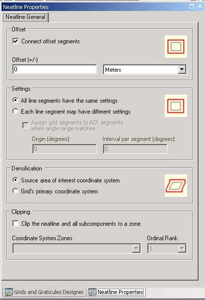
The Neatline Properties dialog box appears.

- Type a value in the Offset (+/-) text box.
- If you want the offset segments to connect to each other, check the Connect offset segments check box.
- Choose the corresponding units for the neatline offset from the source polygon.
- Click the appropriate settings for line segments in the Settings area.
- If you want to assign grid segments to specific sides of an area of interest based on an angle value, type the origin for the angle range in the Origin (degrees) text box.
- Click the appropriate option in the Neatline Densification area.
- If necessary, check the Clip the neatline and all subcomponents to a zone check box.
- Click the Coordinate System Zone drop-down arrow and choose a feature class.