Schematic links are connected to schematic nodes. When the origin and/or end nodes for the links are missing (for example, when the expected extremity node schematic feature classes are not associated with the diagram template, or when the OriginNode and ExtremityNode predefined attributes are not correctly configured for Standard builder diagrams built from custom queries), the schematic links in the diagrams may start/end with no extremity nodes. Then, when applying a schematic layout algorithm on the diagrams, these disconnected links cannot be correctly managed.
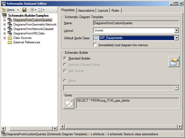
To avoid these potential missing nodes, you can specify any node schematic feature class associated with the diagram template as the default node class so that default extremity nodes are automatically added at the end of the links when needed. Those default nodes will automatically display as any node based on this schematic feature class. The steps below detail how to specify this default node class:
- Edit your schematic dataset within Schematic Dataset Editor.
- If the schematic dataset resources are not arranged in a tree view in the Schematic Items window, click Views in the Schematic Dataset Editor toolbar and click Project Tree.
- In the Schematic Dataset Editor tree, click the entry related to the schematic diagram template for which you want to specify a default node schematic feature class.
- On the Properties tab, click the Default Node Class drop-down list and select the desired node schematic feature class.
Only the node schematic feature classes associated with the diagram template are available in this list. If no node schematic feature classes are associated with the diagram template, the drop-down list is empty. Learn about associating schematic feature classes with diagram templates.

- Click
 Save on the Schematic Dataset Editor toolbar.