Every chart has coordinate information displayed using borders, grids, and/or graticules, indicating to its users the coordinates of where it's located in the world. The grid is also important to navigation, assisting mariners in determining direction and distances traveled. Grids, graticules, (linear) scaled borders, and neatlines are created with grids and graticules tools.
Typically, features are split when crossing the 180th meridian. However, to create grids that span the 180th meridian, a single area of interest feature with a single (part) geometry is required.
ArcGIS for Maritime: Charting comes with preconfigured grids based on the IHO's INT2 standard. These preconfigured grids are delivered as XML files in the following locations:
- For 32-bit Windows operating systems—<Installation location>\Program Files\ArcGIS\MaritimeCharting\Desktop10.3.1\Charting\Cartography\GridDefinitions
- For 64-bit Windows operating systems—<Installation location>\Program Files(x86)\ArcGIS\MaritimeCharting\Desktop10.3.1\Charting\Cartography\GridDefinitions
The following INT2 grids are provided:
Preconfigured grids for the INT2 standard
| File name | Limiting scale | Purpose |
|---|---|---|
INT2_C.xml | N/A | Sheet of plans |
INT2_D.xml | N/A | Inset plan |
|
INT2_E_10K.xml |
Greater than or equal to 1:10,000 |
E grid for large-scale plans |
INT2_E.xml | 1:1 to 1:30,000 | Neatline and geographic grid system for E-scale plans |
INT2_F.xml | 1:30,000 to 1:100,000 | Neatline and calibrated border for 1:30,000- to 1:100,000-scale plans |
INT2_G.xml | 1:100,000 to 1:200,000 | Neatline and calibrated border for 1:100,000- to 1:200,000-scale plans |
INT2_H.xml | 1:200,000 to 1:500,000 | Neatline and calibrated border for 1:200,000- to 1:500,000-scale plans |
INT2_J.xml | 1:500,000 to 1:1,500,000 | Neatline and calibrated border for 1:500,000- to 1:1,500,000-scale plans |
INT2_K.xml | 1:1,500,000 to 1:2,250,000 | Neatline and calibrated border for 1:1,500,000- to 1:2,250,000-scale plans |
INT2_L.xml | 1:2,250,000 to 1:4,750,000 | Neatline and calibrated border for 1:2,250,000- to 1: 4,750,000-scale plans |
INT2_M.xml | 1:4,750,000 and above | Neatline and calibrated border for 1:4,750,000-scale plans and above |
INT2_N.xml | N/A | Noncalibrated border (tick marks only) |
INT2_S.xml | N/A | Secondary/Projected ticks |
INT2_V.xml | N/A | UTM grid and border |
Each grid is created independently using the Make Grids And Graticules Layer geoprocessing tool using a data frame that has the same geographic coordinate system (ensuring that any transformations that are required have been set before the grid is created).
Modifying the data frame properties
Before creating your grids using the standard set of steps, you will need to change your data frame properties so that the central meridian value is not equal to 0 (<> 0). It is recommended that the central meridian value be changed to 180 or a value close to it.
- Click View > Data Frame Properties.
- Click the Coordinate System tab and navigate to the desired coordinate system for your chart.
- Double click the coordinate system to modify the properties.
- Click in the Central_Meridian value field and change the value to 180.
- Click OK to close the Projected Coordinate System Properties dialog box.
- Click OK to close the Data Frame Properties dialog box.
Creating grids
You can make your chart's grid based on an area of interest represented by a preexisting polygon. This polygon may be stored in your product library; it may come from another source, such as a personal database, shapefile, or layer file; or it may be part of your data, already captured as metadata. In any case, you may need to edit this polygon. It is strongly recommended that you double-check that you have permission/privileges to perform edits on the area of interest (AOI) polygon used to make your chart's grid.
- On the main menu, click Customize > Toolbars > Nautical Cartography.
- If necessary, open the Product Library window by clicking Customize > Production > Product Library on the main menu.
A tree view of the product library appears.

- Expand Product Library and Products.
- Navigate to the AOI for the product instance.
- Check the check box next to the AOI.
The AOI feature layer is added to the ArcMap data frame.
- Right-click the AOI feature in the Product Library tree view and click Select.
- On the Nautical Cartography toolbar, click Grids > Make Grids and Graticules Layer.
The Make Grids and Graticules Layer dialog box appears.
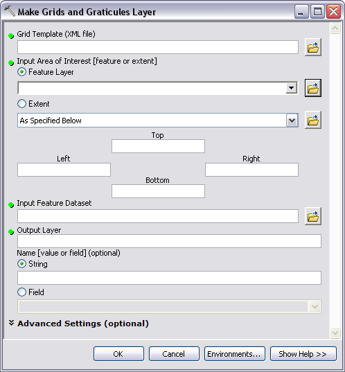
- Click the browse button
 next to the Grid Template (XML file) text box.
 - Navigate to the following location:
- For 32-bit Windows operating systems—<Installation location>\Program Files\ArcGIS\MaritimeCharting\Desktop10.3.1\Charting\Cartography\GridDefinitions
- For 64-bit Windows operating systems—<Installation location>\Program Files(x86)\ArcGIS\MaritimeCharting\Desktop10.3.1\Charting\Cartography\GridDefinitions
- Choose the grid XML that best suits your chart based on purpose and scale.
For example, a chart that has a scale of 1:50,000 would use INT2_F, since the F scale range is 1:30,000 to 1:100,000.
- Click Open.
- For the Input Area of Interest [feature or extent] parameter, use the Feature Layer option and choose the AOI polygon layer from the drop-down list.
- For the Input Feature Dataset parameter, click the browse button
 .
. - Navigate to the Grids feature dataset in your production database.
- Click Add.
You have the option of removing or modifying this grid name or keeping the default.
The Output Layer parameter will be automatically filled with an abbreviation of the grid XML you choose; the Name [value or field] (optional) parameter is also autopopulated. In this instance, it will take the last letter of the grid .xml selected.
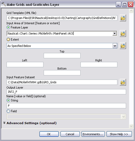
- Expand Advanced Settings (optional).
If there is a warning next to the Mask Size (optional), you can ignore this since it is optional to change the mask size and units.
The Advanced Settings parameters appear.
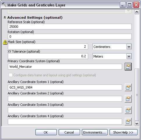
- Change the value in the Reference Scale (optional) text box to that of your chart.
- Click the Properties button
 that is next to Primary Coordinate System (optional).
This will already be populated with World_Mercator.
The Spatial Reference Properties dialog box opens.
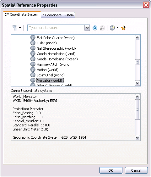
- Double-click Mercator (world) to modify the projection.
- Enter the decimal degree values for the central meridian and standard parallel for your chart.
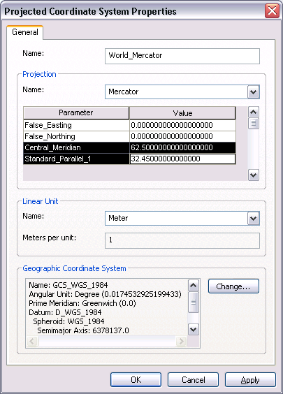
- Click OK to close the Projected Coordinate System Properties dialog box.
- Ensure that the values you entered are now listed on the Spatial Properties dialog box.
- Click OK to close the Spatial Properties dialog box.
- Leave all other advanced settings.
It is optional to change the values for Ancillary Coordinate Systems 1 and 2; however, the grids will be generated without changing these parameters.
- Click OK.
- Once the tool has finished running, click Close to close the Results dialog box.
Grids are added to the top of the Table Of Contents window; be sure to keep them there. After later steps in the guide book, it will be necessary to move the grids back to the top of the list of layers in the Table Of Contents window.
- Examine the grids after they have been added to the Table Of Contents window.
- Save the map document by clicking the Save button
 on the Standard toolbar.
- Close ArcMap.
Once you have finished with these tasks, you will have created a grid that spans the 180th meridian.