Available with Standard or Advanced license.
This topic applies to ArcGIS for Desktop Standard and ArcGIS for Desktop Advanced only.
. This workflow describes the steps for creating a new parcel subdivision.
The workflow uses the sample dataset downloaded with the Tax Parcel Editing map on the ArcGIS Solutions website. To use the automated workflows on the sample data, enable the parcel fabric in the ParcelEditing feature dataset with the Local Government Information Model and drag the parcel fabric into an empty map document.
To start the New Subdivision automated workflow, open the Parcel Workflows dialog box by clicking Parcel Editor > Parcel Workflows. Select New Subdivision and click Begin workflow.
The workflow consists of the components shown in the diagram below:

Subdivision plat and legal description
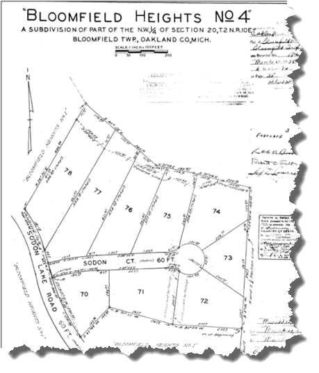
The source plat document for the parcel subdivision is shown below:
The legal description for the new subdivision is:
The land embraced in the annexed plat of "Bloomfield Heights No 4" a subdivision of part of the NW ¼ of Section 20 T2N, R10E Bloomfield Twp, Oakland County Michigan is described as having a point of commencement beginning from the NW corner of the Echowood subdivision and along a bearing of N5°-36'E a distance of 276.6ft to the point of beginning and then along twelve courses and distances starting with N83°54'W - 275.0ft, thence N72°15'W - 262.0ft, thence S47°44'W - 169.96ft, thence a curve to the right (Radius 806.50ft, long chord bears N21°15'W - 290.28ft) a distance of 291.84ft, thence N10°55'W - 85.0ft, then on a curve to the left (Radius 494.62ft, long chord bears N21°27'W - 179.72ft) a distance of 181.18ft, thence N34°30'E - 486.84ft, thence S45°28'E - 360.16ft, thence S73°58'E - 148.85ft, thence S73°04'E - 225.16ft to a point on the N and S ¼ section line; thence S5°58'W along said ¼ section line 168.29ft, thence S5°36'W along said ¼ section line 392.0ft to the point of beginning.
Search for parent parcel
Part of existing tax parcel 1920126036 will be affected by the new subdivision:
- Open the TaxParcelEditingMap document located in the MapsandGeodatabase folder or drag the parcel fabric (enabled with the Local Government Information Model) in the ParcelEditing feature dataset into an empty map document.
- In the Table Of Contents window, make the Tax Parcels layer, Lots and Units layer, Subs and Condos layer, and the Tax Lines Anno layer selectable and visible.
- Search for the tax parcel that will be affected by the new subdivision. In the sample dataset in the TaxParcelEditingMap document, search for parcel 1920126036.
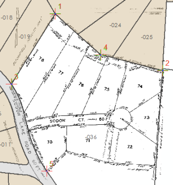
- For visual purposes, it may be helpful to optionally georeference the source plat document into the map:
- Load the plat image into the map and click Customize > Toolbars > Georeferencing to open the Georeferencing toolbar.
- Zoom to the extent of the plat image, click Add Control Points
 on the Georeferencing toolbar, and click on a point in the image that you want to georeference to the parcel fabric.
 - Zoom to the area in the map where you want to georeference the image, and click to snap on a point in the fabric that corresponds to the point on which you clicked on the image.
After your first control point is established, the image will move to the approximate georeferenced location.
- Continue to add control points until the image is accurately georeferenced.
- Click Georeferencing > Update Georeferencing on the Georeferencing toolbar.
For this workflow using the sample data, the visibility of the Historic Parcels layer has been turned off.
Create new plan
A new plan is created before entering the dimensions of the subdivision parcel. The parcel fabric plan represents the legal document recording a parcel merge, subdivision, and so on. Parcels are created in plans, which are managed in the Plan Directory dialog box. If you do not work with plans, you can use the system default map plan.
- Start an edit session and click New Parcel on the Parcel Editor toolbar.
- On the Parcel Details dialog box, click Plan to create a new plan for the subdivision.
- On the Plan Directory dialog box, click Create Plan.
- On the Plan Properties dialog box under the General tab, type the plan name and legal description.
For the workflow using the sample dataset, type Bloomfield Heights as the Name and leave the Description text box empty.
- Click the Record Format tab to specify the plan units.
Choose Quadrant Bearing from the Direction or Angle Type drop-down list, Degrees Minutes Seconds from the Direction and Angle Units drop-down list, US Survey Feet from the Distance and Length Units drop-down list, and Square Feet for the Area Units drop-down list.
Set Circular Curve Parameters to Radius and Arc Length and Circular Curve Direction to Chord.
- Click the Attributes tab to enter attributes, such as the Surveyor, SurveyDate, Accuracy, and so on.
For the workflow using the sample dataset, type 03/17/1955 as the LegalDate, and set Accuracy to 2 - After 1980.
- After entering attributes, click OK on the Plan Properties dialog box to create the new plan.
To change plan properties, right-click the plan on the Plan Directory dialog box and click Properties.
- Click Set as Active Plan on the Plan Directory dialog box to set the plan and return to the Parcel Details dialog box.
Enter subdivision parcel
Enter the subdivision block parcel using the dimensions on the source plat document.
- On the Parcel Details dialog box, click Template to open the Select Feature Template dialog box, and choose the Subdivision feature template under Subs and Condos for the new subdivision parcel.
- Under the Properties tab, change the Sub or Condo Name field to Bloomfield Heights.
- Click the Lines tab to enter parcel dimensions.
- Click to snap on the northwest corner of Echowood subdivision to add it as the first from point in the Lines grid.
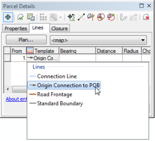
- Click under the Template field and choose the Origin Connection to POB line template.
The template field name is initially collapsed to a single icon. You can expand the field to display the field name, which is Template.
- Click the Bearing field and type 5-36-0-1 (-1 is the NE quadrant-bearing shortcut).
- Press ENTER to move to the Distance field and type a distance of 276.6. Press ENTER to move to the next row in the Lines grid.
- For the second traverse leg, set the line template to Standard Boundary and type a bearing of 83-54-0-4 (-4 is the NW quadrant-bearing shortcut) and a distance of 275.00.
The Standard Boundary line template will be used for the remaining traverse legs.
- Enter the remaining traverse legs as shown below:
- 72-15-0-4, 262.00
- 47-44-0-3, 169.96
- 21-15-0-4, Radius = 806.5, Arc Length = 291.84
- 10-55-0-4, 85.00
- 21-27-0-4, Radius = -494.62 (curve turns to the left), Arc Length = 181.18
- 34-30-0-1, 486.84
- 45-28-0-2 (-2 is the SE quadrant-bearing shortcut), 360.16
- 73-58-0-2, 148.85
- 73-04-0-2, 225.16
- 5-58-0-3 (-3 is the SW quadrant-bearing shortcut), 168.29
- For the final traverse leg, type a bearing of 5-36-0-3 and a distance of 392.00. Change the to point to be the same value as the to point of the first origin connection line to close the parcel. The to point of the final traverse leg and the to point of the origin connection line are the same point.
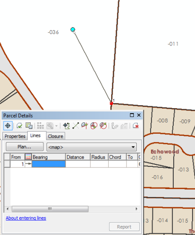
Data entry in the lines traverse grid is designed to work with the 10-key pad, where you can use a single hand to enter dimensions. Use quadrant-bearing shortcuts and press the ENTER key and ARROW keys to move between cells.
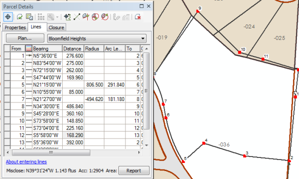
The misclose of the parcel is displayed at the bottom of the Parcel Details dialog box. Large misclosures indicate a possible blunder in the entered dimensions and should be investigated.
Join and align new parcel
When new parcels are added to the parcel fabric, they need to be joined to the parcel fabric to become part of the parcel fabric layer. A newly created parcel is not yet connected to the parcel fabric layer, even if existing fabric points were used as from- or to-points in the creation of the parcel. New parcels need to be joined to the parcel fabric to be connected to the parcel fabric.
Parcel joining is an interactive process where the parcel points of a floating parcel or group of parcels are matched with their corresponding points in the parcel fabric.
- After completing the parcel traverse, click Keep And Join
 on the Parcel Details dialog box.
 Close or dock the Parcel Details dialog box.
- On the Join Parcel dialog box, choose Fabric points held fixed, line points moved to lines under Use the following method when I click OK.
Dimensions entered for this parcel are taken from a plat dated 03/15/1955. The surrounding parcel data has dimensions from more recent plats and is thus considered more accurate than the parcel being joined. For the workflow, the new subdivision parcel is aligned to the more accurate, surrounding parcels. If the parcel being joined is more accurate than the surrounding parcel fabric, you would choose the Joining points held fixed at map position on the Join Parcel dialog box.
- Use the Join a parcel tool
 to join the northwest corner of the subdivision parcel to its corresponding point in the fabric.
Zoom in and click to snap on the subdivision parcel point, then click to snap on the parcel fabric point.
- Zoom to the point of beginning of the parcel and use the Create Join Link tool
 to join the from point of the first origin connection line to the existing point of beginning in the parcel fabric.
Zoom in close to the points and drag a box around the two points. Since the from point of the origin connection line is snapped to the point of beginning in the fabric, these points overlap.
- Use the Trace fabric to create join links tool to join the remaining points to their corresponding points in the parcel fabric:
- Click Trace fabric to create join links and change the Trace buffer to 10 feet.
- Click the southeast corner of the joining parcel, and trace a line counterclockwise around the parcel to the southwest corner. Click to finish tracing.
- Click Create Links to join the points in the trace buffer.
- Click Join on the Join Parcel dialog box to join the new parcel to the parcel fabric using the join links.
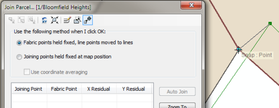
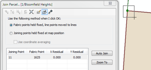
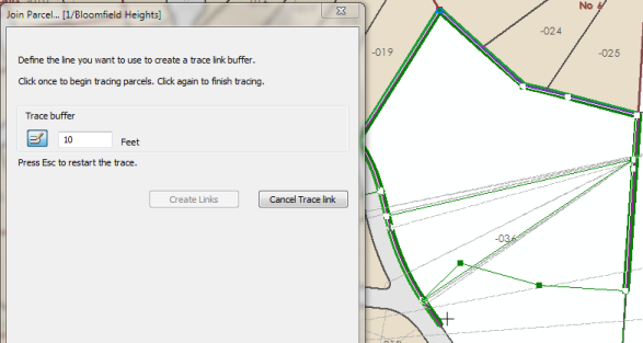
Join residuals are displayed in the Join Parcel dialog box as join links are created. Join residuals are an indication of how well the parcels being joined fit with the surrounding parcels. In the workflow, some residuals are slightly high because the parcel being joined has older, less accurate dimensions than the more recent surrounding parcels.
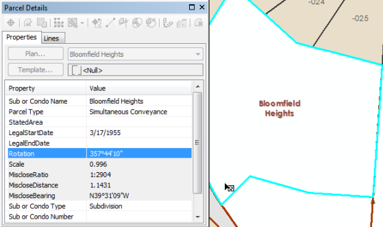
Create remainder parcel
The newly joined subdivision parcel is used to split and create a parcel remainder from existing tax parcel 19-20-126-036:
- Use the selection chip to select the newly joined parcel, right-click and click Parcel Remainder.
- On the Remainder dialog box, leave the plan set to Bloomfield Heights. For the workflow, the remainder parcel is created in the Bloomfield Heights plan.
- Click Template and choose the Tax Parcels feature template from the Select Feature Template dialog box.
- Choose parcel 1920126036 to create a remainder, optionally enter a name for the remainder parcel, and click OK to create the remainder parcel.
Attributes from parent parcel 1920126036 will be transferred to the remainder parcel.
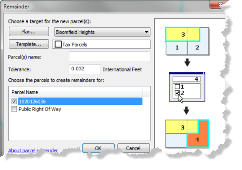
Parent parcel 1920126036 is saved and flagged as historic.
Create lot parcels
Use the dimensions on the source plat to subdivide the Bloomfield Heights subdivision parcel into lot parcels:
- With the Bloomfield Heights subdivision parcel selected, right-click and click Construct from parent.
- Clear the selection of the subdivision parcel.
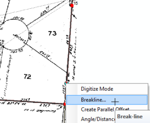
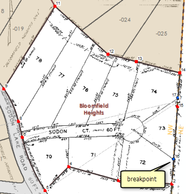
- Right-click the southeastern most boundary (the boundary line that starts at the point of beginning) and click Breakline.
Make sure to right-click near the point of beginning.
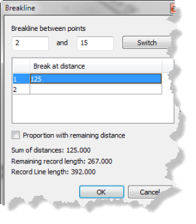
- On the Breakline dialog box, make sure the breakline is going in the right direction, which is from south to north in the sample data. You can click Switch to change the direction of the breakline.
- Click the first field under Break at distance and type 125.00. Press ENTER.
The corner point of lots 72 and 73 lie at a distance of 125.00 feet from the southern endpoint of the subdivision line. Notice that the Remaining record length on the Breakline dialog box is 267.00 feet. This value matches the plat distance of the same line segment on the plat.
- Click OK to create the breakpoint.
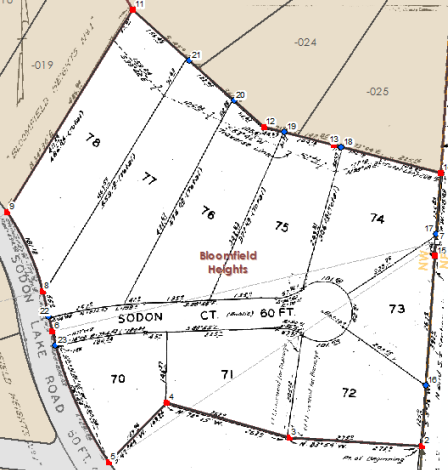
- Add a breakpoint for the corner point of lots 73 and 74:
Right-click and click Breakline on the northeasternmost boundary of the subdivision parcel. Make sure to right-click near the southernmost end point of the line so that the breakline goes from south to north, or from point 15 to point 14. Add a breakpoint at a distance of 42.46 feet. Notice that the Remaining record length on the Breakline dialog box is 125.83 feet. This value matches the plat distance of the same line segment on the plat.
- Add a breakpoint for the corner point of lots 74 and 75:
Break the line between 14 and 13 at a distance of 208.16 feet going in a direction from east to west.
- Add a breakpoint for the corner point of lots 75 and 76.
Break the line between 13 and 12 at a distance of 104.18 feet going in a direction from east to west.
- Add two breakpoints for the corner points of lot 76 and 77 and lots 77 and 78:
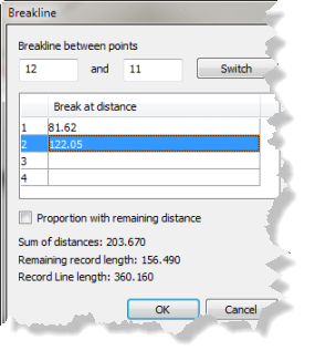
Break the line between 12 and 11 at a distance of 81.62 and add a second distance of 122.05 to create two breakpoints. Break the line in a direction going from east to west.
- Add a breakpoint for the northern corner point of the right-of-way:
Break the line between 8 and 6 at a distance of 55.00 feet going in a direction from north to south.
- Add a final breakpoint for the southern corner point of the right-of-way:
Break the line between 6 and 5 at a distance of 30 feet going in a direction from north to south. From the plan, it can be deduced that point 6 is at the center of the right-of-way (the distance of line between 8 and 6 is 85 feet, and the right-of-way is 60 feet wide).
- Click Parcel Measurement View
 on the Parcel Details dialog box to display the parcel using its entered dimensions, scale, and rotation
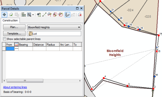
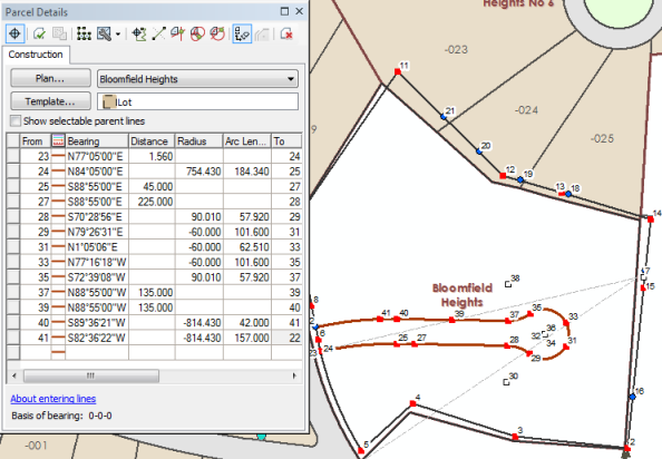
 - Using the Construction tool
 , click the breakpoint added for the southern corner of the right-of-way to add it as the first from point in the Construction grid on the Parcel Details dialog box.
 - Click under the Template field and choose the Road Frontage line template.
- Type a bearing of 77-05-0-1 and a distance of 1.56 for the first, small traverse line.
- The next traverse line is a tangent curve to the first traverse line. Type * in the bearing field to indicate that this bearing is a tangent bearing to the previous traverse line. Type a radius of 754.43 and an arc length of 184.34.
- Enter the remaining traverse legs for the right-of-way parcel as shown below:
- 88-55-0-2, 45.00
- 88-55-0-2, 225.00
- Bearing = * (tangent bearing), Radius = 90.01, Arc Length = 57.92
- Bearing = * (tangent bearing), Radius = -60.00 (curve turns to the left), Arc Length = 101.6
- Bearing = * (tangent bearing), Radius = -60.00 (curve turns to the left), Arc Length = 62.51
- Bearing = * (tangent bearing), Radius = -60.00 (curve turns to the left), Arc Length = 101.6
- Bearing = * (tangent bearing), Radius = 90.01 (curve turns to the left), Arc Length = 57.92
- 88-55-0-4, 135.00
- 88-55-0-4, 135.00
- Bearing = * (tangent bearing), Radius = -814.43 (curve turns to the left), Arc Length = 42.00
- For the final traverse leg, type * as the bearing (tangent bearing), a radius of -814.43, and an arc length of 157.00. The to point of the final traverse leg closes on to the breakpoint added for the northern corner of the right-of-way. Change the to point to be the same value as that of the northernmost breakpoint of the right-of-way.
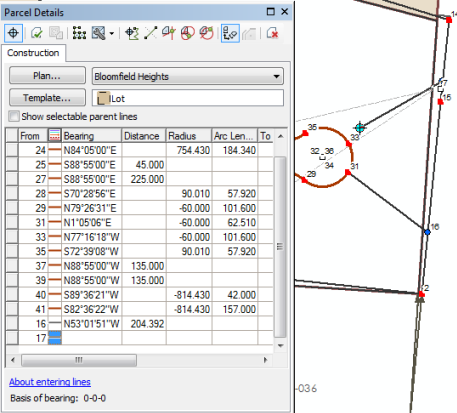
- Add lot parcel split lines between the breakpoints and the right-of-way points:
Click to snap on a breakpoint to add it as the from point in the Construction grid, then click to snap on the appropriate right-of-way point to add it as the to point. If necessary, use the georeferenced plat image as a guide for the correct from and to points to use. Make sure to change the line template to Standard Boundary.
- Under the Construction grid on the Parcel Details dialog box, edit the generated dimensions of the digitized lot lines to match the dimensions of the plat or survey record.
There are only distances specified on the plat. For each line added, change the distance to match the platted distance.
- For the boundary between lots 72 and 73 (line going between point 16 and 31), the plat distance is 203.55.
- For the boundary between lots 73 and 74 (line going between point 17 and 33), the plat distance is 228.75.
- For the boundary between lots 74 and 75 (line going between point 18 and 35), the plat distance is 306.28.
- For the boundary between lots 75 and 76 (line going between point 19 and 39), the plat distance is 377.40.
- For the boundary between lots 76 and 77 (line going between point 20 and 41), the plat distance is 474.02.
- For the boundary between lots 77 and 78 (line going between point 21 and 8), the plat distance is 559.18.
- For the boundary between lots 70 and 71 (line going between point 4 and 27), the plat distance is 146.37.
- For the boundary between lots 71 and 72 (line going between point 3 and 29), the plat distance is 205.12.
- On the Parcel Details dialog box, click Template to open the Select Feature Template dialog box and choose the Lot feature template under Lots and Units for the lot parcels.
- Click the Build Parcels
 arrow on the Parcel Details dialog box and choose Build and keep all Current.
 The original subdivision parcel is saved as a current parcel, and new lot parcels and right-of-way parcels are built from the construction lines. New parcels are named <New parcel> by default.
- As a final cleanup step, merge the curve center points of the right-of-way cul-de-sac into a single center point:
Click the Mean Points tool on the Parcel Editor toolbar and drag a box around the curve center points of the right-of-way cul-de-sac. Accept the default Mean point tolerance and click OK on the Mean Points dialog box.
Attribute parcels
The right-of-way parcel type and name needs to be updated and lot parcel numbers need to be assigned:
- Use the selection chip and the Select Parcel Features tool to select the right-of-way parcel.
On the Parcel Details dialog box under the Properties tab, change Lot or Unit Number to Sodon Ct. Click the drop-down list next to Lot or Unit Type and choose Public Right Of Way.
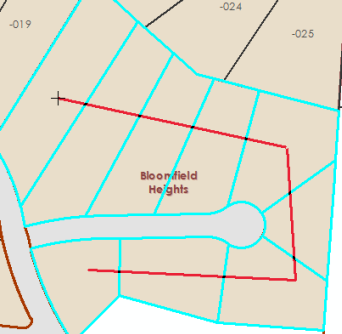
- Use the selection chip and the Select Parcel Features tool to select the new lot parcels.
- Click the Name Parcels tool
 on the Parcel Editor toolbar to sequentially name the new lot parcels.
The tool is used to trace a directional line over a sequence of parcels that determines the order in which the parcels are named.
- Click the southernmost parcel, drag a line east, then click to indicate the end point of the line. Continue dragging the line north and click to indicate the end point. Then, finally, continue dragging a line west and double-click the northernmost parcel to finish the trace.
- On the Parcel sequence naming dialog box, type 70 as the Starting parcel number, leave 1 as the Increment, and click OK
You may need to zoom in to see the newly assigned lot numbers.
Create tax parcels
You can use the duplicate command to duplicate the lot parcels and create tax parcels:
- Use the selection chip and the Select Parcel Features tool to select the lot parcels (exclude the right-of-way parcel).
- Right-click the selected parcels and click Duplicate.
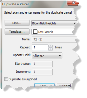
- On the Duplicate a Parcel dialog box, leave the Plan set to Bloomfield Heights.
- Set the Template to Tax Parcels and do not choose Duplicate as unjoined (leave it unchecked).
- Leave the remaining default values and click OK to duplicate the parcels.
Attribute parcels
Use the Name Parcels tool  to sequentially assign names to the tax parcels:
- Select the tax parcels and trace a line counterclockwise over the parcels.
- On the Parcel sequence naming dialog box, type 1920127001 as the Starting parcel number, leave 1 as the Increment, and click OK.
Annotate parcels
The final step of the workflow is to annotate the tax parcel lines:
- Make sure the Tax Lines Anno layer is turned on in the Table Of Contents window.
- With the tax parcels selected (it may be easier to turn off the selectability of the Lots and Units and Subs and Condos layers), click the Annotate Parcel Courses tool
 on the Parcel Editor toolbar.
 - Select ParcelDimensions - 1:1200 on the Annotate Selected Features dialog box and click OK.
- If necessary, use the Edit Annotation Tool
 to edit and change the placement of the generated annotation.
In the TaxParcelEditingMap document, new annotation is not automatically created when new parcels are added.
Annotation is created using the Annotate Parcel Courses tool  , which handles the duplication of annotation on parcel lines.