In this topic
- About the config.xml file
- Understanding the button XML
- Understanding the tool XML
- Understanding the tool palette XML
- Understanding the toolbar XML
- Understanding the menus XML
- Understanding the combo boxes XML
- Understanding the dockable window XML
- Understanding the application extension XML
About the config.xml file
This topic guides you through a high-level discussion on the add-in editor's source view. The XML configuration file is almost identical for each of the ArcGIS for Desktop products supported by the add-in framework; therefore, this topic only illustrates ArcMap as an example. The places where the desktop application defines a difference is noted in the topic. Finally, each example uses simple scenarios to avoid cluttering the discussion. This topic is broken out into sections that match each of the how to topics that describe the workflow for defining your add-ins.
When creating an add-in project, as discussed in How to create an add-in project in Eclipse, there are various properties that you have the ability to set (for example, add-in project name, description, and so on). The properties defined under the add-in overview section of the Eclipse add-in editor view essentially represent the project's metadata, and is used in various places for end users using your customizations.
Behind the scenes, when the values of the properties are being completed, the editor is generating XML that can be viewed in the source view of the config.xml file. For example, if an ArcMap project is created and properties are set for all of the required and optional parameters, the add-in and source views will resemble the following screen shot:

The preceding screen shot represents the graphical user interface (GUI) view of the editor for the config.xml file. The sample GUI is represented as follows in the source view:
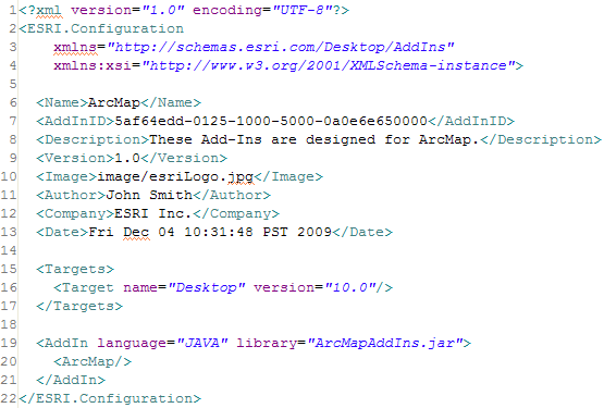
Take a moment to do a quick comparison between the GUI and the XML. You will notice that many of the XML tags match what is shown on the GUI. However, some additional items are added to describe the software version the add-in will be used with as a couple examples. Line numbers have been included on the screen shot and will be referenced in the discussion that describes these additional tags.
- Line 7 represents a globally unique identifier (GUID) that is system generated. This GUID should never be edited or modified because it is used internally by the ArcGIS framework.
- Line 15 uses the target tag to define that the add-in is for ArcGIS for Desktop and with version 10 of the software.
It is not possible to specify ArcGIS Engine as the target instead of ArcGIS for Desktop. The add-in framework is currently only supported with ArcGIS for Desktop products (specifically ArcMap, ArcCatalog, ArcGlobe, and ArcScene).
- Line 19 identifies the language type that is used to define the business logic for the specific add-in types. Since this is an add-in designed in Eclipse using Java, the value of the language attribute is Java. It is also possible to develop add-ins using the Microsoft .NET framework (VB .NET and C# languages are both supported). The second attribute represents the library, in the case of Java, the Java archive (JAR) file that will be created when the add-in is deployed. This name must match the .jar file that is created during deployment.
- Line 20 is used to distinguish the ArcGIS for Desktop product that the add-in project is designed for. When creating an Eclipse add-in project, you are asked to select which product you want to develop add-ins for. After that selection is made, the appropriate XML tag is generated to represent that product. Similarly, ArcCatalog, ArcGlobe and ArcScene will have a different tag to represent the desktop product respectively.
- Line 2 and 22 represent the root tag for add-ins and is used by the ArcGIS framework when interpreting the XML that describes your add-ins.
The XML syntax image is syntactically colored to make the XML more readable; however, the source view uses a normal text editor and syntax highlighting is not available.
Once a project is defined and set up, the next step in the workflow is to define your customizations. Each section discusses each individual type of add-in and explores the available topic examples.
Understanding the button XML
When creating a button, there are various properties that are set in the Button Details section of the editor. The properties defined under the Button Details represent the static information of your add-in. Behind the scenes, the XML is being generated to represent these static properties. For example, if an add-in button is created and defined with the following parameters, the add-in and source views will resemble the following screen shot:
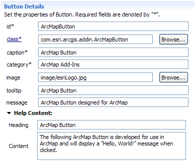
The preceding screen shot represents the add-in view of the add-in editor for the config.xml file when defining the properties for a button. The same GUI is represented as follows in the source view:
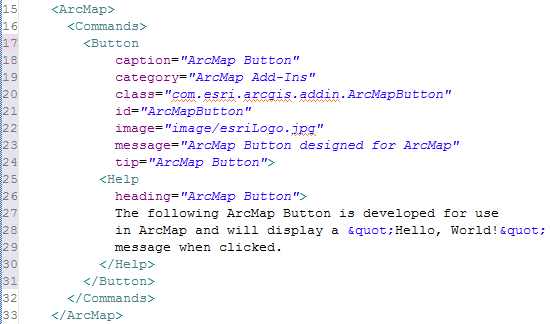
Take a moment to do a quick comparison between the GUI and the XML. Notice that many of the XML tags and attributes match what is shown on the GUI. Notice that the XML that defines the button is wrapped in the ArcMap tag. The following descriptions use specific line numbers to highlight some additional features of the displayed XML:
- Line 16 uses a commands tag to encapsulate all add-ins that are considered to be commands (for example, buttons, tools, and so on).
- Line 17 identifies the button with the button tag. All the properties that are completed are attributes of the button tag (see lines 18-24).
- Line 25-30 defines the context-sensitive Help. Notice that this tag is contained between the opening and closing button tags.
Understanding the tool XML
When creating a tool, there are various properties that are set in the Tool Details section of the add-in editor. The properties defined under the Tool Details section represent the static information of your add-in. Behind the scenes, the XML is being generated to represent these static properties. For example, if a tool is created and defined with the following parameters, the add-in and source views will resemble the following screen shot:
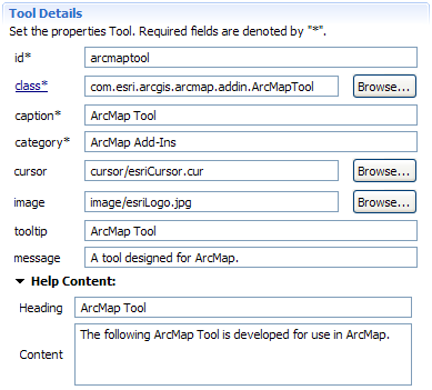
The preceding screen shot represents the add-in view of the editor for the config.xml file when defining the properties for a tool. The sample GUI is represented as follows in the source view:
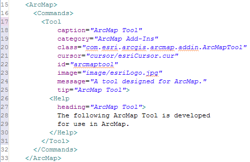
Take a moment to do a quick comparison between the GUI and the XML. Notice that many of the XML tags and attributes match what is shown on the GUI. Notice that the XML that defines the tool are wrapped in the ArcMap tags. The following descriptions use specific line numbers to highlight some additional features of the displayed XML:
- Line 16 uses a commands tag to encapsulate all add-ins that are considered to be commands (for example, buttons, tools, and so on).
- Line 17 identifies the tool with the tool tag. All the properties that are completed are attributes of the tool tag (see lines 18-25).
- Line 26-30 illustrates how the context-sensitive Help is defined. This tag is contained between the opening and closing tool tags.
Understanding the tool palette XML
When creating tool palette, there are various properties that are set on the Tool Palette Details section of the add-in editor. The properties defined on the Tool Palette Details section represent the static information of your add-in. Behind the scenes, the XML is generated to represent these static properties. For example, if a tool palette is created and defined with the parameters on the following screen shot, the add-in and source views will resemble the following:
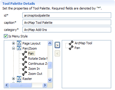
The preceding screen shot represents the add-in view of the editor for the config.xml file when defining the properties for a tool palette. The same GUI is represented as follows in the source view:
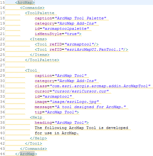
Take a moment to do a quick comparison between the GUI and the XML. Notice that many of the XML tags and attributes match what is shown on the GUI. Notice that the XML that defines the tool palette with the opening and closing ArcMap tags. The following descriptions use specific line numbers to highlight some additional features of the displayed XML:
- Line 17 and 26 defines the tool palette. The tool palette is contained within the command tags. Since any tool palette is really a container for tools, this location is logical.
- Line 22 and 25 uses the item tags to represent tools (whether it is ESRI defined tools or your own add-in tools) that will be contained in the tool palette.
- Line 23 is used to identify the add-in tool previously created in the tool description. Notice that the tool's id property is used to identify it.
- Line 24 is used to identify an ESRI provided tool. In this instance, the pan navigation tool was used. The syntax for the id is discovered and placed in the XML for you. This presents another advantage for using the editor instead of directly defining the XML.
Understanding the toolbar XML
When creating a toolbar, there are various properties that are set on the Toolbar Details section of the add-in editor. The properties defined under the Toolbar Details section, represent the static information of your add-in. Behind the scenes, the XML is generated to represent these static properties. For example, if an add-in toolbar is created and defined with the following parameters, the add-in and source views will resemble the following:
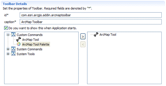
The preceding screen shot represents the add-in view of the editor for the config.xml file when defining the properties for a toolbar. The same GUI is represented as follows in the source view:
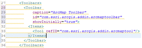
Take a moment to do a quick comparison between the GUI and the XML. Notice that many of the XML tags and attributes match what is shown on the GUI. Notice the XML that defines the toolbar. The following descriptions use specific line numbers to highlight some additional features of the displayed XML:
- Line 27 and 36 defines the toolbar or toolbars. These tags are not contained within the commands' tags (as done for tools, buttons, and so on). Toolbars are contained within the ArcMap tags.
- Line 28 and 35 are used to define an individual toolbar. In this instance, there is only one toolbar defined in the project.
- Line 32 and 34 are used to define items that can be contained on a toolbar. A toolbar can contain buttons, tools, menus, tool palettes, and combo boxes. The preceding screen shot only references a tool; however, it could represent each one of the items mentioned.
- Line 33 is used to identify a tool. Similarly, if other items were added, this tag and attribute would be repeated for each tool added to the toolbar.
Understanding the menu XML
When creating a menu, there are a number of properties that are set on the Menu Details section of the add-in editor. The properties defined under the Menu Details section represent the static information of your add-in. Behind the scenes, the XML is generated to represent these static properties. For example, if a menu is created and defined with the parameters on the following screen shot, the add-in and source views will resemble the following:
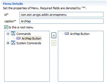
The preceding screen shot represents the add-in view of the editor for the config.xml file when defining the properties for a menu. The same GUI is represented as follows in the source view:

Take a moment to do a quick comparison between the GUI and the XML. Notice that many of the XML tags and attributes match what is shown on the GUI. Notice the XML that defines the menu. The following descriptions use specific line numbers to highlight some additional features of the displayed XML:
- Line 35 and 44 defines the menus. These tags are not contained within the command or toolbar tags (as done for tools, buttons, and so on). Menus are contained within the ArcMap tags.
- Line 36 and 43 are used to define an individual menu. In this instance, there is only one menu defined in the project.
- Line 40 and 42 are used to define items that can be contained on a menu. A menu can contain buttons or other menus. The previous example only references a button; however, it could represent each one of the items mentioned.
- Line 41 is used to identify the button. Similarly, if other items were added, this tag and attribute would be repeated for each item added to the menu.
Understanding the combo box XML
When creating a combo box, there are various properties that are set on the Combo Box Details section of the add-in editor. The properties defined under the Combo Box Details section represent the static information of your add-in. Behind the scenes, the XML is generated to represent these static properties. For example, if a combo box is created and defined with the parameters on the following screen shot, the add-in and source views will resemble the following:
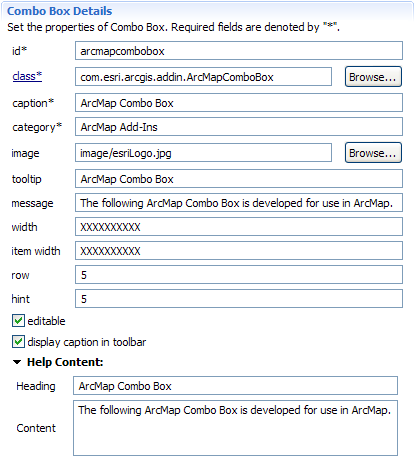
The preceding screen shot represents the add-in view of the editor for the config.xml file when defining the properties for a combo box. The same GUI is represented as follows in the source view:
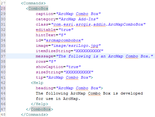
Take a moment to do a quick comparison between the GUI and the XML. Notice that many of the XML tags and attributes match what is shown on the GUI. Notice the XML that defines the combo box. The following descriptions use specific line numbers to highlight some additional features of the displayed XML:
- Line 28 and 47 illustrates that the combo box is contained within the command tags. All elements between define an individual combo box.
Understanding the dockable window XML
When creating a dockable window, there are various properties that are set on the Dockable Window Details section of the add-in editor. The properties defined under the Dockable Window Details section represent the static information of your add-in. Behind the scenes, the XML is generated to represent these static properties. For example, if a dockable window is created and defined with the parameters on the following screen shot, the add-in and source views will resemble the following:
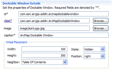
The preceding screen shot represents the add-in view of the editor for the config.xml file when defining the properties for a dockable window. The same GUI is represented as follows in the source view:
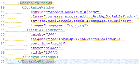
Take a moment to do a quick comparison between the GUI and the XML. Notice that many of the XML tags and attributes match what is shown on the GUI. Notice the XML that defines the dockable window. The following descriptions use specific line numbers to highlight some additional features of the displayed XML:
- Line 48 and 61 defines the dockable window.
- Line 49 through 60 are used to define an individual dockable window.
- Line 56 defines the neighbor of this dockable window. The ESRI add-in Wizard discovered the id and assigned it accordingly within the XML.
Understanding the application extension XML
When creating an application extension, there are various properties that are set on the Extension Details section of the add-in editor. The properties defined under the Extension Details section represent the static information of your add-in. Behind the scenes, the XML is generated to represent these static properties. For example, if an application extension is created and defined with the parameters on the following screen shot, the add-in and source views will resemble the following:
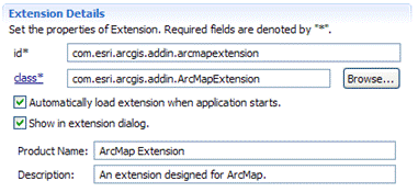
The preceding screen shot represents the add-in view of the editor for the config.xml file when defining the properties for an application extension. The sample GUI is represented as follows in the source view:
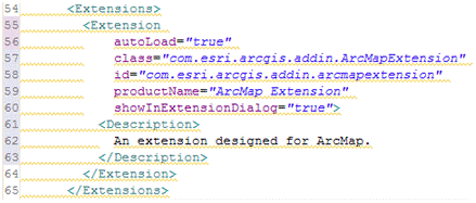
Take a moment to do a quick comparison between the GUI and the XML. Notice that many of the XML tags and attributes match what is shown on the GUI. Notice the XML that defines the application extension. The following descriptions use specific line numbers to highlight some additional features of the displayed SML:
- Line 54 and 65 defines the application extension.
- Line 55 through 64 are used to define an individual application extension.
See Also:
How to create an add-in buttonHow to create an add-in tool
How to create an add-in combo box
How to create an add-in toolbar
How to create an add-in tool palette
How to create an add-in menu
How to create an add-in dockable window
How to create an add-in application extension
| Development licensing | Deployment licensing |
|---|---|
| ArcGIS for Desktop Basic | ArcGIS for Desktop Basic |
| ArcGIS for Desktop Standard | ArcGIS for Desktop Standard |
| ArcGIS for Desktop Advanced | ArcGIS for Desktop Advanced |