获得 Production Mapping 许可后可用。
The point component creates a two-dimensional lattice of points that are the intersection of two virtual grid lines. One of the grid lines has an orientation of north–south, and the other is oriented east–west. Points can be used to create ticks, crosshairs, and Military Grid Reference System (MGRS) coordinates. Annotation can be created from points.
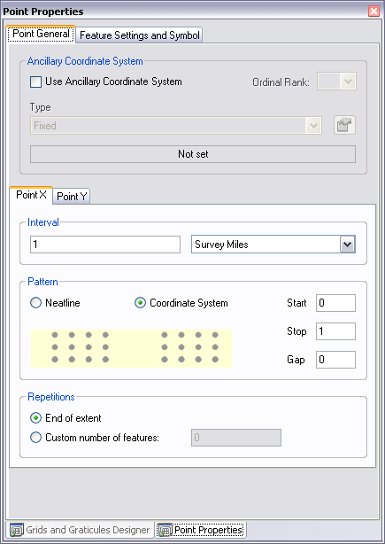
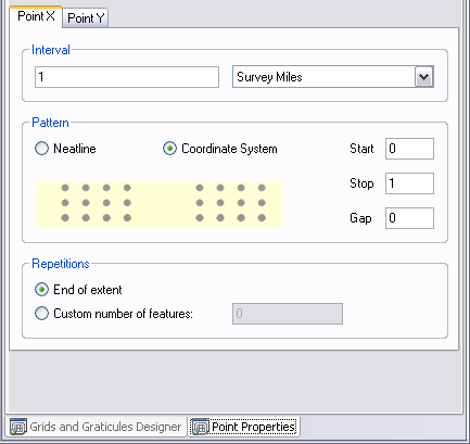
Pattern settings for points include:
- Neatline—Point patterns start at the grid's neatline.
- Origin of point's coordinate system—Point pattern starts at the origin of the grid's coordinate system.
In the geodatabase feature class for points (PNT), each point has fields, TEXT_X and TEXT_Y, that store the coordinate location for that point. The values that are stored with the point feature are the actual coordinate values based on the specified coordinate system for the corresponding linear feature.
Repetition settings for points include:
- End of Extent—Pattern continues to the end of the area of interest.
- Custom—You specify the number of repetitions.
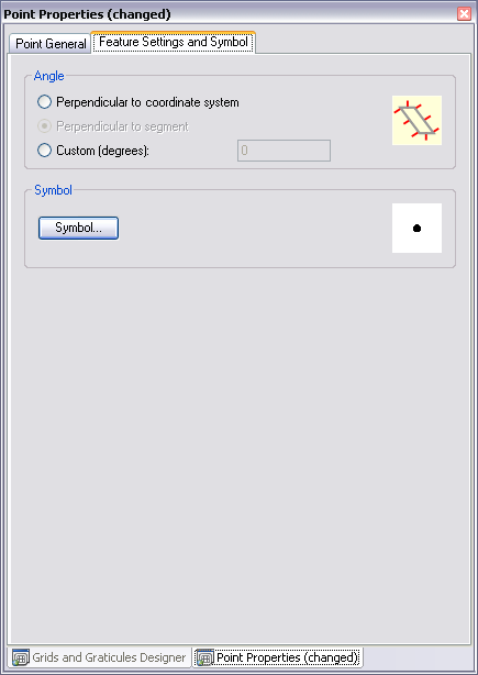
On the Feature Settings and Symbol tab, you can specify an angle for the rotation of each point feature's symbol. Angle settings include:
- Perpendicular to Coordinate System—Automatically created based on coordinate system.
- Perpendicular to Segment—Automatically created based on the segment.
- Custom—You set the angle.
On the Feature Settings and Symbol tab, you can choose a symbol from the Representation Rule Selector dialog box.
- Start ArcMap.
- On the main menu, click Customize > Toolbars > Production Cartography to add the Production Cartography toolbar.
- Click the Grids and Graticules Designer window button
 on the Production Cartography toolbar.
 - Create or load a grid.
- Right-click the Neatline component and click Add > Points.
The Points component is added to the tree view.
- Right-click the Points component in the tree view and click Properties.
The Points Properties window appears.

- If necessary, do the following to define an ancillary coordinate system:
- Check the Use Ancillary Coordinate System check box in the Ancillary Coordinate System area.
- Click the Type drop down list and choose an ancillary coordinate system type.
- If necessary, click the Spatial Reference Properties button
 .
.
- Choose a coordinate system to use as the ancillary coordinate system.
- Click OK.
- If necessary, click the Point X tab on the bottom of the Point Properties tab.

- Type the number of units in the Interval text box.
- Choose the unit of measurement to use with the interval.
- Choose an option in the Pattern area.
- Type a value in the Start text box.
- Type a value in the Stop text box.
- Type a value in the Gap text box.
- Choose an option in the Repetitions area.
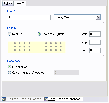
- Click the Point Y tab.

- Type the number of units in the Interval text box.
- Choose the unit of measurement to use with the interval.
- Choose an option in the Pattern area.
- Type a value in the Start text box.
- Type a value in the Stop text box.
- Type a value in the Gap text box.
- Choose an option in the Repetitions area.
- Click the Feature Settings and Symbol tab.

- Choose an option in the Angle area.
- If the Custom option has been chosen, type a value in the Custom (Degrees) text box.
- Click Symbol.
The Representation Rule Selector dialog box appears.
- Choose a symbol and set the appropriate symbol properties.
- Click OK.