- Engine
- ArcGIS for Desktop Basic
- ArcGIS for Desktop Standard
- ArcGIS for Desktop Advanced
- Server
Additional library information: Contents, Object Model Diagram
To use the code in this topic, reference the following assemblies in your Visual Studio project. In the code files, you will need using (C#) or Imports (VB .NET) directives for the corresponding namespaces (given in parenthesis below if different from the assembly name):
- ESRI.ArcGIS.Geodatabase
- ESRI.ArcGIS.GeoDatabaseDistributed
- ESRI.ArcGIS.Geometry
- ESRI.ArcGIS.System (ESRI.ArcGIS.esriSystem)
The Geodatabase library provides the application programming interface (API) for the geodatabase. The geodatabase is a repository of geographic data built on standard industry relational and object relational database technology. The objects in the library provide a unified programming model for all supported data sources in ArcGIS. The Geodatabase library defines many of the interfaces that are implemented by data source providers higher in the architecture.
The geodatabase can be extended by developers to support specialized types of behavior in the geodatabase, for example, through class extensions. In addition, the API can be used to consume custom vector data sources added using plug-in data sources. The native data types supported by the geodatabase cannot be extended.
See the following sections for more information about this namespace:
- Core geodatabase
- Geometric network
- Topology
- Data elements
- TIN
- Data transfer
- Versioning
- Archiving
- Name objects
- Relationship query table
- Raster
- Metadata
- Plug-in data sources
- Network dataset
- Representation class
Core geodatabase
The core geodatabase objects are detailed in the following diagram:
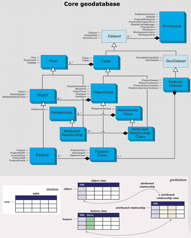
This diagram is a simplified view of the most important geodatabase objects, which are summarized as follows:
- Workspace in the geodatabase data model corresponds to a geodatabase, an ArcInfo coverage workspace, or a folder with shapefiles.
- Dataset is the highest level data container.
- Geodataset is a dataset that contains geographic data.
- FeatureDataset is comprised of feature classes, geometric networks, and topologies.
- Table is a collection of rows that have attributes stored in columns.
- Row is a record in a table. All rows in a table share the same set of fields.
- ObjectClass is a type of table that stores non-spatial objects.
- Object is a row with an object identifier.
- FeatureClass is a type of object class that stores spatial objects.
- Feature is an object with a geometric shape.
- RelationshipClass represents relationships through embedded foreign keys.
- Relationship is an association between objects or features; it controls behavior when objects or features are moved or deleted.
- AttributedRelationshipClass is a type of table that stores relationships.
- AttributedRelationship can represent many-to-many relationships as well as attributes on relationships.
Workspaces
A workspace is a container of spatial and non-spatial datasets such as feature classes, raster datasets, and tables. It provides methods to instantiate existing datasets and to create new datasets. The following diagram details the workspace objects:
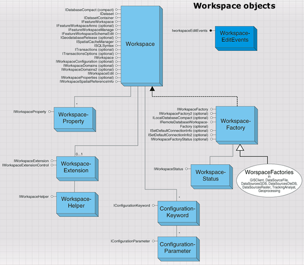
Workspaces are classified into types specified by the esriWorkspaceType enumeration: esriFileSystemWorkspace, esriLocalDatabaseWorkspace, and esriRemoteDatabaseWorkspace.
Shapefiles and ArcInfo workspaces are examples of esriFileSystemWorkspace. File geodatabases and personal geodatabases are examples of esriLocalDatabaseWorkspace. An enterprise geodatabase stored in a relational database management system (RDBMS)—such as Oracle, DB2, SQL Server, or Informix—and accessed via ArcSDE is an example of esriRemoteDatabaseWorkspace.
Other workspace types include the following:
- Raster workspace—Contains grids and images.
- TIN workspace—Contains triangulated irregular networks (TINs).
- CAD workspace—Contains computer-aided design (CAD) drawings.
- VPF workspace—Contains Vector Product Format (VPF) data.
A workspace factory is a dispenser of workspaces and allows a client to connect to a workspace using a set of connection properties, a path on the file system, or a connection string. A workspace represents a database or a data source that contains one or more datasets. Examples of datasets include tables, feature classes, and relationship classes. Various workspace factory types are shown in the following diagram:

Workspace factories are singleton classes with public constructors. They maintain a pool of currently connected, active workspaces that are referenced by the application. Connection properties are specified using a PropertySet object and can be saved to a connection file.
The examples in this library overview instantiate workspace factories using the Activator.CreateInstance method rather than the new keyword. This is because workspace factories are singleton Component Object Model (COM) classes. For more information, see Interacting with singleton objects.
Workspace factories also support methods that can be used to browse and manage file system workspaces and to manage connection files for remote database workspaces.
The following code example connects to an ArcSDE for Oracle geodatabase:
[C#] // Create a property set with connection properties.
IPropertySet propertySet=new PropertySetClass();
propertySet.SetProperty("SERVER", "cuillin");
propertySet.SetProperty("INSTANCE", "esri_sde");
propertySet.SetProperty("USER", "scott");
propertySet.SetProperty("PASSWORD", "tiger");
propertySet.SetProperty("VERSION", "SDE.DEFAULT");
propertySet.SetProperty("AUTHENTICATION_MODE", "DBMS");
// Create an SDE workspace factory and open the workspace.
Type factoryType=Type.GetTypeFromProgID("esriDataSourcesGDB.SdeWorkspaceFactory");
IWorkspaceFactory workspaceFactory=(IWorkspaceFactory)Activator.CreateInstance
(factoryType);
IWorkspace workspace=workspaceFactory.Open(propertySet, 0);
' Create a property set with connection properties.
Dim propertySet As IPropertySet=New PropertySetClass()

propertySet.SetProperty("SERVER", "cuillin")

    propertySet.SetProperty("INSTANCE", "esri_sde")

        propertySet.SetProperty("USER", "scott")

            propertySet.SetProperty("PASSWORD", "tiger")

                propertySet.SetProperty("VERSION", "SDE.DEFAULT")

                    propertySet.SetProperty("AUTHENTICATION_MODE", "DBMS")

                        ' Create an SDE workspace factory and open the workspace.
                        Dim factoryType As Type=Type.GetTypeFromProgID("esriDataSourcesGDB.SdeWorkspaceFactory")
                        Dim workspaceFactory As IWorkspaceFactory=CType(Activator.CreateInstance(factoryType), IWorkspaceFactory)
                        Dim workspace As IWorkspace=WorkspaceFactory.Open(propertySet, 0)
The IFeatureWorkspace interface is used to access and manage datasets that are key components of a feature-based geodatabase: tables, object classes, feature classes, feature datasets, and relationship classes.
All of the Open methods, such as OpenTable, take a dataset name as input. When working with an ArcSDE geodatabase, the name can be fully qualified (for example, database.owner.tablename or owner.tablename) using the qualification character appropriate to the underlying database (see ISQLSyntax). If the input name is not fully qualified, then it is qualified using the currently connected user for the workspace. When working with geodatabases (personal, file, or ArcSDE), the workspace keeps a running object table of instantiated datasets. Multiple calls to open an already instantiated dataset will return a reference to the already instantiated dataset.
The OpenTable method can be used to open any existing table or object class in the workspace given its fully qualified name. The table object returned will always support the ITable interface. The returned table object will support additional interfaces depending on the type of table—for example, object classes will additionally support the IObjectClass interface.
The OpenFeatureClass method can be used to open any existing feature class in the workspace given its fully qualified name. Every feature class in a geodatabase has a unique, fully qualified name, and the OpenFeatureClass method can be used to directly open feature classes that are part of a feature dataset.
The following code example opens a shapefile as a feature class:
[C#] // Create a shapefile workspace factory and open a folder of shapefiles as a workspace.
Type factoryType=Type.GetTypeFromProgID(
"esriDataSourcesFile.ShapefileWorkspaceFactory");
IWorkspaceFactory workspaceFactory=(IWorkspaceFactory)Activator.CreateInstance
(factoryType);
IWorkspace workspace=workspaceFactory.OpenFromFile(@"C:\Data\USA", 0);
// Use the IFeatureWorkspace interface to open a shapefile.
IFeatureWorkspace featureWorkspace=(IFeatureWorkspace)workspace;
IFeatureClass featureClass=featureWorkspace.OpenFeatureClass("States");
// Write the number of features to the console.
Console.WriteLine("Feature Count: {0}", featureClass.FeatureCount(null));
' Create a shapefile workspace factory and open a folder of shapefiles as a workspace.
Dim factoryType As Type=Type.GetTypeFromProgID("esriDataSourcesFile.ShapefileWorkspaceFactory")
Dim workspaceFactory As IWorkspaceFactory=CType(Activator.CreateInstance(factoryType), IWorkspaceFactory)
Dim workspace As IWorkspace=workspaceFactory.OpenFromFile("C:\Data\USA", 0)

' Use the IFeatureWorkspace interface to open a shapefile.
Dim featureWorkspace As IFeatureWorkspace=CType(workspace, IFeatureWorkspace)
Dim featureClass As IFeatureClass=featureWorkspace.OpenFeatureClass("States")

' Write the number of features to the console.
Console.WriteLine("Feature Count: {0}", featureClass.FeatureCount(Nothing))
Applications can use the ISQLSyntax interface to help construct Structured Query Language (SQL) queries and where clauses that are database-system independent.
GetSpecialCharacter can be used to return the database management system (DBMS)-dependent character that represents esriSQLSpecialCharacters, including the following:
- esriSQL_WildcardManyMatch ( % in SQL_92, * in Jet 4.0)
- esriSQL_WildcardSingleMatch ( _ in SQL_92, ? in Jet 4.0)
- esriSQL_DelimitedIdentifierPrefix ( " in SQL-92, [ in Jet 4.0)
- esriSQL_DelimitedIdentifierSuffix (" in SQL-92, ] in Jet 4.0)
Applications should use the ParseTableName and ParseColumnName methods to split the fully qualified name for a dataset or for a column in a table into its components (database, owner, table, column). Applications that are to be RDBMS agnostic should not assume that "." is the delimiter used to separate the components of a fully qualified dataset name. Both the IDataset.Name property for a dataset in a geodatabase and the IDatasetName.Name property for a dataset name object return the fully qualified name for the dataset (the name object for the dataset, obtained using the IDataset.FullName property).
Applications should use the QualifyTableName and QualifyColumnName methods to construct fully qualified dataset and column names.
Editing data
Applications can use specified transactions to manage direct updates, for example, any feature class that is tagged as not requiring an edit session can be updated outside an edit session. When using transactions to manage direct updates, applications are responsible for discarding any cached row objects at transaction boundaries.
ITransactions is an optional interface that allows an application to explicitly control database transactions. The interface does not support nested transactions. Applications should not use transactions when performing updates within an edit session. In the context of an edit session, transactions are managed by the workspace and are automatically started and stopped as needed.
Applications should be aware that Data Definition Language (DDL) operations made through the ArcObjects geodatabase data access objects (for example, deleting a feature dataset or creating a new feature class) use database transactions to ensure integrity of the data dictionary tables and commit the transaction at the end of the operation. Applications should not invoke DDL operations within an application transaction—application transactions should be restricted to Data Manipulation Language (DML) operations (such as data updates).
Applications can use geodatabase edit sessions to manage database transactions. It is possible to start an edit session in one of two modes. The IWorkspaceEdit interface allows the application to start and stop edit sessions in the versioned edit session mode only. A versioned edit session is begun using the StartEditing method. The withUndoRedo parameter can be used to suppress undo/redo logging if the workspace supports such suppression. Shapefiles support suppression of undo/redo logging, but ArcSDE does not.
The IMultiuserWorkspaceEdit interface also allows the application to start and stop edit sessions during which the objects in a geodatabase can be updated. This differs from the IWorkspaceEdit interface in that the IMultiuserWorkspaceEdit interface is only supported by workspaces that support both edit session modes, namely ArcSDE geodatabases. For this reason, use the IMultiuserWorkspaceEdit interface only if it is your intent to control the edit session mode used when editing. By default, through the StartEditing method, an edit session will be started in the versioned edit session mode. Therefore, it is necessary to use the IWorkspaceEdit interface to edit local workspaces.
If the IMultiuserWorkspaceEdit interface is used, the edit session can be started in either versioned or nonversioned edit session modes. If the edit session mode is set to versioned, the only changes to data that an application detects within an edit session are changes that are made by that application. Changes made by other concurrently executing applications (if allowed) are not detected until the edit session is saved or discarded. On the other hand, editing within an edit session in nonversioned mode is the equivalent of performing standard database transactions. You still perform the edits within a standard edit session; however, when you’ve finished, the changes are committed as a single transaction by saving. If you don’t want to commit the changes, you abort the edit session without saving. Each transaction can include as few or as many operations as required, provided they fall within a single edit session.
Editing in a nonversioned edit session mode alters the data source directly; it does not store the changes in delta tables as versioned editing does. This avoids the overhead of managing these extra tables and allows you to easily adapt non-Esri applications so that they can read and edit the data. The drawback is that since you edit the data source directly, you cannot undo or redo an individual edit if you make a mistake. The only way to undo edits is to undo all edits by quitting the edit session without saving. You can perform nonversioned edits on simple data only: points, lines, polygons, annotation, and relationships. You cannot perform nonversioned edits on complex data, such as feature classes in a topology or geometric network.
If undo/redo facilities are required when editing in a versioned edit session mode, all related changes to objects in the database within an edit session should be grouped into edit operations. An edit operation is started using the StartEditOperation method. Applications are responsible for calling the AbortEditOperation method to abort an edit operation if errors are detected within the methods executed for an edit operation. Applications are responsible for calling StopEditOperation to mark the end of a successfully completed edit operation. Completed edit operations can be thought of as being pushed onto an undo stack.
The UndoEditOperation method can be used to roll the state of the edit session back to what it was prior to the execution of the edit operation at the top of the undo stack. Undoing an edit operation removes the edit operation from the undo stack and adds it to a redo stack. The RedoEditOperation method rolls the state of the edit session forward to what it was after the execution of the edit operation at the top of the redo stack, removes the redone edit operation from the redo stack, and pushes it back onto the undo stack. Performing a new edit operation clears the redo stack.
The StopEditing method is used to end an edit session. The saveEdits parameter controls whether or not edits are saved or discarded. A multiversioned database can support multiple concurrent edit sessions on the same version of the database. In such a scenario, StopEditing will return an error code of FDO_E_VERSION_REDEFINED if it detects that the database state associated with the version being edited is no longer the same as it was at the beginning of the edit session (indicating that the version was modified by some other edit session). In this case, the application is responsible for calling the IVersionEdit.Reconcile method to reconcile the edit session against the current state of the version being edited. StopEditing can be called again after reconciliation.
The geodatabase guarantees "unique instancing" of row objects retrieved from the database within an edit session. Any data access call that retrieves a nonrecycling object with a particular object ID will return the in-memory instance of the object if the object has already been instantiated by the application. Such behavior ensures application correctness when updating complex object models—for example, models with relationship-based messaging or models with network features where updates to the geometry of a feature affect the geometry of topologically related features.
The following code example shows a simple nonversioned edit session on an ArcSDE workspace. Note that if you undo the edit operation, there will be no outstanding edits, so the prompt to save the work will not appear. For this reason, all object editing should be done within an edit session. The geodatabase data access APIs (such as IRow.Store, ITable.Update, and ITable.Insert) will fail if you attempt to use them outside an edit session on object and feature classes that are marked as requiring an edit session to ensure unique instancing semantics. Use IObjectClassInfo2.CanBypassEditSession to determine the situation.
[C#] // Create a set of connection properties.
IPropertySet propertySet=new PropertySetClass();
propertySet.SetProperty("SERVER", "bigsky");
propertySet.SetProperty("INSTANCE", "5151");
propertySet.SetProperty("USER", "gdb");
propertySet.SetProperty("PASSWORD", "gdb");
propertySet.SetProperty("VERSION", "sde.DEFAULT");
// Create a workspace factory and connect to the geodatabase.
Type factoryType=Type.GetTypeFromProgID("esriDataSourcesGDB.SdeWorkspaceFactory");
IWorkspaceFactory workspaceFactory=(IWorkspaceFactory)Activator.CreateInstance
(factoryType);
IWorkspace workspace=workspaceFactory.Open(propertySet, 0);
// Open the feature class to be edited.
IFeatureWorkspace featureWorkspace=(IFeatureWorkspace)workspace;
IFeatureClass featureClass=featureWorkspace.OpenFeatureClass("States");
// Start a non-versioned edit session on the workspace.
IWorkspaceEdit workspaceEdit=(IWorkspaceEdit)featureWorkspace;
IMultiuserWorkspaceEdit muWorkspaceEdit=(IMultiuserWorkspaceEdit)featureWorkspace;
muWorkspaceEdit.StartMultiuserEditing
(esriMultiuserEditSessionMode.esriMESMNonVersioned);
// Within an edit operation, retrieve and delete a single feature.
workspaceEdit.StartEditOperation();
IFeature feature=featureClass.GetFeature(1);
feature.Delete();
workspaceEdit.StopEditOperation();
// Stop editing, specifying that the edit should be saved.
// Use a value of false here to discard edits.
workspaceEdit.StopEditing(true);
' Create a set of connection properties.
Dim propertySet As IPropertySet=New PropertySetClass()

propertySet.SetProperty("SERVER", "bigsky")

    propertySet.SetProperty("INSTANCE", "5151")

        propertySet.SetProperty("USER", "gdb")

            propertySet.SetProperty("PASSWORD", "gdb")

                propertySet.SetProperty("VERSION", "sde.DEFAULT")

                    ' Create a workspace factory and connect to the geodatabase.
                    Dim factoryType As Type=Type.GetTypeFromProgID("esriDataSourcesGDB.SdeWorkspaceFactory")
                    Dim workspaceFactory As IWorkspaceFactory=CType(Activator.CreateInstance(factoryType), IWorkspaceFactory)
                    Dim workspace As IWorkspace=workspaceFactory.Open(propertySet, 0)

                    ' Open the feature class to be edited.
                    Dim featureWorkspace As IFeatureWorkspace=CType(workspace, IFeatureWorkspace)
                    Dim featureClass As IFeatureClass=featureWorkspace.OpenFeatureClass("States")

                    ' Start a non-versioned edit session on the workspace.
                    Dim workspaceEdit As IWorkspaceEdit=CType(featureWorkspace, IWorkspaceEdit)
                    Dim muWorkspaceEdit As IMultiuserWorkspaceEdit=CType(featureWorkspace, IMultiuserWorkspaceEdit)
                    muWorkspaceEdit.StartMultiuserEditing(esriMultiuserEditSessionMode.esriMESMNonVersioned)

                    ' Within an edit operation, retrieve and delete a single feature.
                    workspaceEdit.StartEditOperation()
                    Dim feature As IFeature=featureClass.GetFeature(1)
                    feature.Delete()
                    workspaceEdit.StopEditOperation()

                    ' Stop editing, specifying that the edit should be saved.
                    ' Use a value of false here to discard edits.
                    workspaceEdit.StopEditing(True)
The rules for correct object editing on a geodatabase are summarized as follows:
- All object editing should be done within an edit session.
- Group changes into edit operations.
- Discard all references to row objects retrieved at the edit session boundary (on StartEditing). If references to row objects will be maintained across edit operations, discard all references and refetch objects in response to the undo, redo, and abort edit operation calls made by the application, as well as the reconcile call made within an edit session on versioned databases. In the context of ArcMap, these calls are made by the Editor, which broadcasts corresponding editor events via the IEditEvents and IEditEvents2 interfaces. Personal and ArcSDE geodatabase workspaces support the IWorkspaceEditEvents and IVersionEvents outbound interfaces and directly broadcast these events.
- Use nonrecycling search cursors to fetch objects that are to be updated (using any of the Search, GetRow, or GetRows methods supported by tables, feature classes, and selection sets). Recycling search cursors should only be used for drawing and read-only access to object states.
- Always fetch all properties of the objects to be edited. Query filters should always use "*" for the subfields property (attempts to instantiate nonrecycling cursors with less than all fields will still result in all row object fields being hydrated).
- After changing a row object, call the IRow.Store method to mark the object as changed and trigger propagation of the OnChanged method; propagate messages to related objects by calling the IRow.Store method on the object. Delete objects by calling the IRow.Delete method on the object, which triggers the OnDelete method. Stored and deleted objects within an edit operation are automatically and periodically flushed to the underlying database as needed to ensure read/query consistency and update efficiency. Use the set versions of these methods (for example, IRowEdit.DeleteSet) if updates or deletions are made to a set of objects to increase performance.
- Update and insert cursors are bulk data-loading and data-update APIs designed to perform direct updates and inserts outside an edit session on simple data during the data-loading phase of a project. Following the editing rules in this section will help ensure geodatabase integrity, particularly where custom objects and geodatabase behavior is concerned. Avoid using these APIs in editing applications. Using these APIs within an edit session, on complex objects (objects with nonsimple row or feature behavior), or on objects participating in composite relationships or relationships with notification negates any performance advantages they may have.
Workspace extensions
A workspace representing a geodatabase can have one or more workspace extensions. A workspace extension extends the functionality of a workspace in some way, for example, by managing a new type of custom dataset or by maintaining custom data dictionary information on datasets. A workspace extension is usually used in conjunction with an application or editor extension that acts as the client of the workspace extension.
The workspace instantiates all workspace extensions that are registered in the component category CATIDs.GeodatabaseWorkspaceExtensions at connect time. An application extension can find a workspace extension by its globally unique identifier (GUID) and invoke methods supported by the extension as appropriate. It will also instantiate all workspace extensions registered with a workspace using IWorkspaceExtensionManager.RegisterExtension.
IWorkspaceExtension is a mandatory interface that must be supported by all workspace extensions. The GUID property returns the GUID for the extension and is guaranteed to be unique. The Name property is the name of the extension. The PrivateDatasetNames and DataDictionaryTableNames properties return the names of tables and datasets that are private to the extension and will not be exposed to browsing clients by the workspace.
Datasets
Dataset is an abstract class that represents a named collection of data in a workspace. Datasets can contain other datasets. All datasets support the IDataset interface and can optionally support other interfaces, including IDatasetEdit, ISchemaLock, and IMetadata.
The following diagram details the dataset objects:

Examples of datasets include tables, feature classes, relationship classes, feature datasets, topologies, and geometric networks. Datasets appear as items in the ArcCatalog table of contents (TOC) under their workspace as shown in the following screen shot:

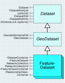
Feature datasets are collections of feature classes and can contain relationship classes and controller datasets such as geometric networks and topologies. Feature classes that store simple features can be organized either inside or outside a feature dataset. Those outside a feature dataset are called stand-alone feature classes. Feature classes that store topological features, for example, those participating in geometric networks or topologies, must be contained within a feature dataset to ensure a common spatial reference. A feature dataset is a dataset that exists only in a geodatabase workspace; all the datasets contained in a feature dataset are also part of the same geodatabase.
The FeatureDataset class is shown in the following diagram:
Each dataset in a geodatabase must have a unique name. In particular, each feature class in a geodatabase must have a unique name independent of the feature dataset that contains it. This is different from a file system model, where two folders can contain files with the same local name within the folder.
When programming with feature classes, remember that the feature class may or may not belong to a feature dataset.
The following code example shows how to get the workspace for a feature class and assumes a feature dataset exists and therefore may fail:
[C#] // This excerpt won't work for stand-alone feature classes.
IFeatureDataset featureDataset=featureClass.FeatureDataset;
IWorkspace workspace=featureDataset.Workspace;
' This excerpt won't work for stand-alone feature classes.
Dim featureDataset As IFeatureDataset=featureClass.FeatureDataset
Dim workspace As IWorkspace=featureDataset.Workspace
The following code example works for both stand-alone feature classes and those in feature datasets:
[C#] IDataset dataset=(IDataset)featureClass;
IWorkspace workspace=dataset.Workspace;
Dim dataset As IDataset=CType(featureClass, IDataset)
Dim workspace As IWorkspace=dataset.Workspace
Table, ObjectClass, and FeatureClass objects
Table, ObjectClass, and FeatureClass objects are detailed in the following diagram:
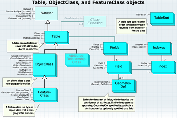
A table has one or more columns, referred to as fields, and contains an unordered collection of rows. For each field, each row has exactly one value in the data type of the field.
A table is a dataset; properties such as the name of the table, the name object for the table, and the workspace containing the table can be obtained via the IDataset interface. In relational terms, a Table object represents an RDBMS table or view. In object-oriented terms, a Table object represents an ObjectClass or a RelationshipClass in a geodatabase. A Table object hands out Row objects that support application-callable methods depending on the type of data stored in the table. The Name property of a Table, accessible via the IDataset interface, returns its fully qualified name. The level of qualification can vary depending on the host DBMS. For example, a table named "pipes" owned by a user named "gas" may be called "pipes" in a file geodatabase, "gas.pipes" on Oracle, and "mydb.gas.pipes" on SQL Server. The ParseTableName method on the ISQLSyntax interface supported by the table’s workspace can be used to split the fully qualified name into its components.
The Table class is shown in the following diagram:

An object class is a table whose rows represent entities, modeled as objects with properties and behaviors. The row objects handed out by an ObjectClass instance support the IRow and the IObject interfaces.
An object class can participate in any number of relationship classes (IObjectClass.RelationshipClasses) that relate its instances to objects (entities) in other object classes. ObjectClass can contain a discriminating field, referred to as the subtype field, that can be used to partition its instances into a number of subtypes. All subtypes share the same field definition and are stored in the same table; however, individual subtypes can differ in the default values and domains assigned to fields. The subtyping mechanism can also be used in defining attribute, connectivity, and topology rules that apply to the instances of the object class. The subtyping mechanism is a lightweight alternative to creating multiple subclasses, and each is represented by its own ObjectClass.
ObjectClass has an object class ID that is unique within the geodatabase. This ObjectClassID property is assigned to ObjectClass at the time it is created or at the time that an existing table in the RDBMS is registered with the geodatabase as an object class. The name of the object class is the same as the name of the table in the DBMS in which the objects in the object class are stored; it follows the same fully qualified naming conventions.
ObjectClass can have an AliasName property that is stored as part of its definition by the geodatabase. AliasName can be retrieved and used for display purposes by applications.
The ObjectClass object is shown in the following diagram:
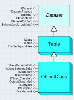
Although all objects in a FeatureClass or ObjectClass must have the same behavior and attributes, not all objects have to share the same default values and validation rules. You can group features and objects into subtypes. Subtypes differentiate objects based on their rules.
A FeatureClass is an ObjectClass whose objects are features, that is, a feature class is a collection of spatial entities, modeled as objects with properties and behaviors. All the features in a feature class share the same attribute schema (they have the same set of named fields). The row objects handed out by a feature class support the IRow, IObject, and IFeature interfaces.
A feature class has one distinguished field of type Geometry, referred to as the shape field. The shape field stores the geometry (referred to as the ShapeType property) for the features in the FeatureClass.
The FeatureClass object is shown in the following diagram:
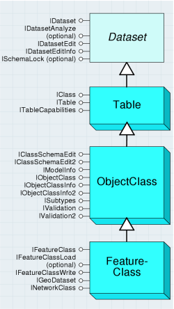
The following code example uses a workspace object to return a FeatureClass object:
[C#] // Create a File GDB workspace factory and open a File GDB as a workspace.
Type factoryType=Type.GetTypeFromProgID(
"esriDataSourcesGDB.FileGDBWorkspaceFactory");
IWorkspaceFactory workspaceFactory=(IWorkspaceFactory)Activator.CreateInstance
(factoryType);
IWorkspace workspace=workspaceFactory.OpenFromFile(@"C:\Data\USA.gdb", 0);
// Use the IFeatureWorkspace interface to open a feature class.
IFeatureWorkspace featureWorkspace=(IFeatureWorkspace)workspace;
IFeatureClass featureClass=featureWorkspace.OpenFeatureClass("States");
' Create a File GDB workspace factory and open a File GDB as a workspace.
Dim factoryType As Type=Type.GetTypeFromProgID("esriDataSourcesGDB.FileGDBWorkspaceFactory")
Dim workspaceFactory As IWorkspaceFactory=CType(Activator.CreateInstance(factoryType), IWorkspaceFactory)
Dim workspace As IWorkspace=workspaceFactory.OpenFromFile("C:\Data\USA.gdb", 0)

' Use the IFeatureWorkspace interface to open a feature class.
Dim featureWorkspace As IFeatureWorkspace=CType(workspace, IFeatureWorkspace)
Dim featureClass As IFeatureClass=featureWorkspace.OpenFeatureClass("States")
Row, Object, and Feature objects
The following diagram details the Row, Object, and Feature objects:
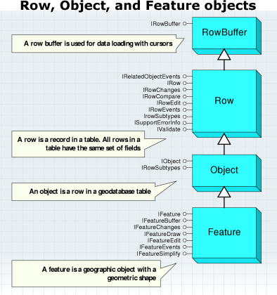
A RowBuffer object is a transient object that is capable of holding the state of a row but has no object identity. It is used primarily during data loading as the argument to the InsertRow method on an insert cursor. RowBuffer is obtained from a Table using the CreateRowBuffer method.
The IRowBuffer interface contains methods to access the state (the set of field values) for RowBuffer. These methods take as an argument the numeric index of the field to be accessed.
The RowBuffer and Row objects are shown in the following diagram:
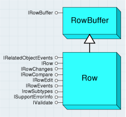
A Row object is an instantiated software object that represents a persistent row in a table. A Row object is normally obtained from a cursor on a table (for example, ICursor.NextRow) or fetched directly given its object ID (for example, ITable.GetRow).
Once retrieved, clients can query the Row object for additional interfaces and invoke methods on the Row object. The CLSID property of a table determines the type of row object returned by the table. A new persistent Row object is created using the ITable.CreateRow method. The act of creating the row assigns its identity. Applications should use the CreateRow method to create persistent Row objects, as opposed to directly cocreating the Row objects. The latter will not create a row in the underlying persistent store.
A row has a set of fields. The set of fields for a row is the same as the set of fields for its table. In particular, the numeric index of a field in the fields collection of its table is the same as the numeric index of the field in the fields collection of the row, which is the same as the numeric index used to access the value of the field from the row. This means that application programs can and should cache field numeric indexes using the FindField method on the Table object, rather than invoking the FindField method once per row returned by a Cursor.
The following code example shows the creation of a row, then an update, followed by the deletion of the row:
[C#] // Find the position of any fields that will be edited.
int fieldIndex=table.FindField("Name");
// Create a new row.
IRow row=table.CreateRow();
row.set_Value(fieldIndex, "Exploits");
row.Store();
// Update the row.
row.set_Value(fieldIndex, "Badger");
row.Store();
// Delete the row.
row.Delete();
' Find the position of any fields that will be edited.
Dim fieldIndex As Integer=table.FindField("Name")

' Create a new row.
Dim row As IRow=table.CreateRow()
row.Value(fieldIndex)="Exploits"
row.Store()

' Update the row.
row.Value(fieldIndex)="Badger"
row.Store()

' Delete the row.
row.Delete()
An Object object is a Table whose Row objects represent entities. The Row objects handed out by an Object object support the IRow and the IObject interfaces and are referred to simply as Objects. Another name for the Object object in this context is Entity object.
The IObject interface is almost identical to IRow, from which it inherits. The only additional property is a direct link to the Object class.
The instances of an Object can be partitioned into a number of subtypes. The IRowSubtypes interface on an Object contains methods that allow determination and modification of the subtype to which an Object belongs, as well as initialization or resetting of the field values of an Object to the default values defined for its subtype.
The Object object is shown in the following diagram:

When Objects are programmatically created via the CreateRow method on the ITable interface (or for features with the CreateFeature method on the IFeatureClass interface), the default subtype is not automatically set, nor are the default values initialized. When using ArcMap, these tasks are automatically performed. However, if you are programmatically creating an Object (or Feature) that has default values, the following code example indicates the proper sequence that should be followed:
[C#] // Get the default subtype code for the feature class.
ISubtypes subtypes=(ISubtypes)featureClass;
int defaultSubtype=subtypes.DefaultSubtypeCode;
// Create a new feature.
IFeature feature=featureClass.CreateFeature();
// Set the subtype and initialize the default values for the feature.
IRowSubtypes rowSubtypes=(IRowSubtypes)feature;
rowSubtypes.SubtypeCode=defaultSubtype;
rowSubtypes.InitDefaultValues();
' Get the default subtype code for the feature class.
Dim subtypes As ISubtypes=CType(featureClass, ISubtypes)
Dim defaultSubtype As Integer=subtypes.DefaultSubtypeCode

' Create a new feature.
Dim feature As IFeature=featureClass.CreateFeature()

' Set the subtype and initialize the default values for the feature.
Dim rowSubtypes As IRowSubtypes=CType(feature, IRowSubtypes)
rowSubtypes.SubtypeCode=defaultSubtype
rowSubtypes.InitDefaultValues()
A Feature object is a spatial object. It is also a member of a feature class, being a row in the feature class table. A feature has an associated shape, the type of which is defined by the feature class. The possible shape objects are Point, Multipoint, Multipatch, Polyline, and Polygon—these are all objects in the Geometry object model.
The Feature object is shown in the following diagram:
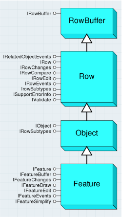
Typically, you will deal with simple features, but there are various special kinds as defined by the esriFeatureType enumeration. These include annotation, dimension, raster catalog, and various network features.
The IFeature interface extends IObject and IRow, from which it inherits. The additional facilities have to do with the shape of the feature. You can use the Shape property to get or set the shape. This is more convenient than using the Value property, since you don’t have to work out the index of the shape field.
At 9.3, the GeometryServer class was added to the Geodatabase library. GeometryServer lets clients programmatically apply common geometric operations to arrays of geometry objects. Buffering, projection of geometries from one spatial reference system to another, and evaluation of spatial relations are some of the operations provided. For more information, see the IGeometryServer interface (located in the Geometry library) as well as the Geometry library overview.
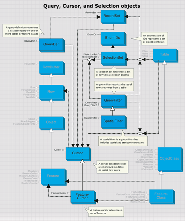
Query, Cursor, and Selection objects
The Query, Cursor, and Selection objects are detailed in the following diagram:
Cursors
A Cursor object is a data-access object that can be used either to iterate over the set of rows in a table or to query or insert new rows into a table. There are three types of cursors, referred to as search, insert, and update cursors. Each of these types of cursors is returned by the corresponding method (Search, Insert, or Update) on a Table or FeatureClass object. The Search and Update methods take a QueryFilter object as input, which can be used to restrict the set of rows returned.
A search cursor can be used to retrieve rows specified by a query filter; it supports a NextRow method. An update cursor can be used to positionally update and delete rows specified by a query filter; it supports the NextRow, UpdateRow, and DeleteRow methods. An insert cursor is used to insert rows into a table and supports the InsertRow method. All these methods are available in the single ICursor interface—it is your responsibility to make the calls appropriate to the type of cursor.
The NextRow method on a search or update cursor returns the next row in the result set to the application. The Row object returned is allocated and hydrated by the cursor, and a reference to it is handed to the application. To retrieve all rows in a result set containing N rows, the application must make N calls to NextRow.
Cursors are forward only; they do not support backing up and retrieving rows that have already been retrieved nor do they support making multiple passes over data. If an application needs to make multiple passes over the data, the application must reexecute the query that returned the cursor. If both executions of the query are made within the same edit session (or database transaction with the appropriate level of isolation), the application is guaranteed not to detect any changes made to the data by other concurrently executing applications.
The following code example shows a simple cursor operation. It prints out the value of the first field for each row in a table.
[C#] // Create a recycling cursor to return every row.
ICursor cursor=table.Search(null, true);
// Iterate through the cursor's rows, writing the values to the console.
IRow row=null;
while ((row=cursor.NextRow()) != null)
{
Console.WriteLine(row.get_Value(0));
}
' Create a recycling cursor to return every row.
Dim cursor As ICursor=table.Search(Nothing, True)

' Iterate through the cursor's rows, writing the values to the console.
Dim row As IRow=cursor.NextRow()
While Not row Is Nothing
    Console.WriteLine(row.Value(0))
    row=cursor.NextRow()
End While
No data is fetched from the database until the NextRow method is called.
A Cursor object has a recycling property that controls how it allocates Row objects. Recycling cursors allocate a single Row object and rehydrate it on each fetch. They can be used to optimize read-only access, for example, when drawing. You cannot maintain a reference on a Row object returned by a recycling cursor across multiple calls to NextRow on the cursor. Row objects returned by a recycling cursor should not be modified. Nonrecycling cursors return a separate Row object on each fetch. The objects returned by a nonrecycling cursor can be modified (setting the IRowBuffer.Value property or any other custom ancestor supported by Row) and stored with polymorphic behavior. The geodatabase guarantees unique instance semantics on nonrecycling row objects fetched during an edit session. If the Row object to be retrieved by a call to NextRow has already been instantiated in the calling application, a reference to the existing row object will be returned.
All Row objects retrieved from a table using a cursor logically contain the same ordered set of fields, and this set is the same as the ordered set of fields for the cursor and the table. In particular, the numeric index of a field in the fields collection of the table is the same as the numeric index of the field in the fields collection of the cursor, which is the same as the numeric index of the field for the row. So, the FindField method needs to be used only once per table or cursor. If the query filter used in generating a cursor does not include certain fields, the resulting row objects will still logically contain these fields; however, they will not have hydrated values for these fields. If an application accesses these field values for the row, a variant of type empty (VT_EMPTY) will be returned. This value is different from the Null value (VT_NULL) that is returned when the value of a fetched field is null.
The UpdateRow method can be used to update the row at the current position of an update cursor (making a call to NextRow on a cursor returns a row and positions the cursor on that row). After fetching a Row object using NextRow, the application can modify the row as needed, then call UpdateRow, passing in the modified row. This is an alternative to calling Store on the retrieved row. Using a recycling update cursor can be faster than calling Store on the rows returned by a search cursor when performing direct updates outside an edit session on simple data. If the Row objects for the table are not simple (they do not have custom behavior or participate in composite relationships or relationships with notification), calling UpdateRow on the cursor will generate a call to Store on the Row object to trigger the custom behavior, and there will be no performance gain.
The DeleteRow method can be used to delete the row at the current position of an update cursor (that is, to delete the row returned by the last call to NextRow on this cursor). After fetching a Row object using NextRow, the application should call DeleteRow on the cursor to delete the row. The application is responsible for discarding the deleted Row object. Using a recycling update cursor to delete rows can be faster then calling Delete on the rows returned by a search cursor when performing direct updates outside an edit session on simple data. If the Row objects for the table are not simple (they do not have custom behavior or participate in composite relationships or relationships with notification), calling DeleteRow on the cursor will generate a call to Delete on the Row object to trigger the custom behavior, and there will be no performance gain.
Insert cursors are used to bulk insert rows. Using an insert cursor offers significantly faster performance for data loading into simple tables and feature classes (tables whose CLSID is esriGeoDatabase.Row, esriGeoDatabase.Object, or esriGeoDatabase.Feature) than the alternative: making multiple calls to CreateRow on the table followed by calling Store on the created row.
Insert cursors on tables that contain non-simple objects internally use the CreateRow and Store methods to achieve polymorphism, and there is no difference in performance in these cases. The InsertRow method takes RowBuffer as an argument. Applications obtain RowBuffer using the CreateRowBuffer method on the Table object into which rows are to be inserted. Each call to InsertRow on the cursor creates a new row in the database whose initial values are set to the values in the input row buffer. The object ID for the created row is returned by the InsertRow method.
The useBuffering method argument to the Insert method on a table returns an insert cursor that buffers rows on the clients and sends them to the server in batches for increased performance. The application is responsible for calling Flush on the insert cursor after all rows have been inserted. If a call to Flush is not made, the cursor will flush its buffers on destruction (when the application releases all references on the cursor). However, relying on the destructor to flush the insert cursor does not give the application the chance to detect errors that may arise on the call to flush (for example, if the tablespace [disk] for the table in the underlying database fills up).
The FeatureCursor object is a kind of Cursor object. It performs in the same way, except it's based on a feature class rather than a generic table. The FeatureCursor object is shown in the following diagram:
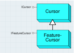
The IFeatureCursor interface provides access to a set of features in a feature class. It operates in the same way as ICursor, although it does not inherit from that interface. This saves you from using query interface (QI) when dealing with features rather than rows.
There is a direct relationship between the methods on the various interfaces of Cursor objects and feature cursors as shown in the following graphic:

Query filters and spatial filters
A QueryFilter object specifies a filter for tabular data based on attribute values. It's used to restrict the set of rows or the set of columns retrieved from a single table or feature class. The primary use of a query filter is to specify the set of rows to be returned when opening a cursor on a table. It is also used in a number of other cases where a subset of the data in a table needs to be specified.
Some scenarios of using QueryFilter include opening a cursor on rows in a table, selecting features in ArcMap, deleting features meeting certain criteria, counting the number of features satisfying a condition, and defining which features will be rendered on the map.
The following code example shows how to select features for the State of California. This code will work on any feature class with a STATE_NAME attribute—QueryFilters are not specific to any particular dataset.
[C#] // Create the query filter and apply a where clause.
IQueryFilter queryFilter=new QueryFilterClass();
queryFilter.WhereClause="STATE_NAME='California'";
// Select the features with a STATE_NAME of "California".
ISelectionSet selectionSet=featureClass.Select(queryFilter,
esriSelectionType.esriSelectionTypeIDSet,
esriSelectionOption.esriSelectionOptionNormal, null);
' Create the query filter and apply a where clause.
Dim queryFilter As IQueryFilter=New QueryFilterClass()
queryFilter.WhereClause="STATE_NAME='California'"

' Select the features with a STATE_NAME of "California".
Dim selectionSet As ISelectionSet=featureClass.Select(queryFilter, esriSelectionType.esriSelectionTypeIDSet, esriSelectionOption.esriSelectionOptionNormal, Nothing)
There is no need to specify a WhereClause if you only want to filter the fields of data. You can also use a null value in place of QueryFilter for those methods that require one.
For example, the following code example shows how to find the number of features in a feature class (without applying any constraints):
[C#] Console.WriteLine("Feature Count: {0}", featureClass.FeatureCount(null));
Console.WriteLine("Feature Count: {0}", featureClass.FeatureCount(Nothing))
You can use the SubFields property to improve performance when using query filters. The performance gain comes from fetching only the field values that you require rather than all the data for each row. The default value for SubFields is "*", which indicates that all field values will be returned. It is not necessary to set the subfields when the query filter is used in a context in which no attribute values are fetched, for example, when selecting features.
QueryFilter has properties on the IQueryFilter interface named SubFields and WhereClause and represents a subset of the single table queries that can be made against a table in a SQL database using the SQL SELECT statement. QueryFilters map to simple SQL select statements of the form SELECT <field names> FROM <table name> WHERE <where-clause that references only table name>.
The SQL syntax used to specify the WhereClause of QueryFilter objects is the same as that of the underlying database holding the data. An application can use the ISQLSyntax interface on a workspace to determine information about the SQL syntax used, such as the delimiter character used in qualifying table and field names and the identifier quote character. This information is available for the different types of workspaces (ArcSDE for Oracle, ArcSDE for SQLServer, Access, shapefile, coverage, and others). Unlike QueryDef objects, QueryFilter objects are supported across all workspace types, including shapefiles and coverages.
A SpatialFilter object is a QueryFilter object that includes both spatial and attribute constraints. SpatialFilter can be used to restrict the set of features retrieved from a feature class using both spatial and attribute restrictions. A spatial filter has a single query geometry that specifies the geometry against which the features in the feature class will be tested. Because ArcObjects supports a number of different geometry types, including both single and multipart geometries and geometry collections, one way of expressing a complex spatial query is by building an appropriate query geometry to pass as input to the spatial filter.
The QueryFilter and SpatialFilter objects are shown in the following diagram:

A spatial filter has a single geometric shape that is used in the query. You can form more complicated spatial queries by using several spatial filters in succession.
You can use spatial filters anywhere that query filters are used, as long as the dataset to be queried has a spatial field. The following are example tasks:
- Selecting features that overlap a search area
- Finding features near another feature
- Defining a limited geographic area for feature display
The ISpatialFilter interface is used to define a query with geographic criteria. You must always set these three properties: Geometry, GeometryField, and SpatialRel. The GeometryEx property can be used to set the query geometry in the case of large query geometries where the application is willing to surrender ownership of the geometry to the filter. In this case, the filter can modify (project) the query geometry in place if the spatial reference of the query geometry is different from the native spatial reference of the feature class or the requested output spatial reference. The spatial reference in which the features should be returned by the query is specified using the OutputSpatialReference property on the IQueryFilter interface.
The following code example shows a simple selection of features that intersect a given shape. It assumes an existing feature class and a valid geometry (perhaps derived from end user input).
[C#] // Create the filter.
ISpatialFilter spatialFilter=new SpatialFilterClass
{
Geometry=geometry, GeometryField=featureClass.ShapeFieldName, SpatialRel =
esriSpatialRelEnum.esriSpatialRelIntersects
};
// Select the features that satisfy the filter's constraints.
ISelectionSet selectionSet=featureClass.Select(spatialFilter,
esriSelectionType.esriSelectionTypeIDSet,
esriSelectionOption.esriSelectionOptionNormal, null);
' Create the filter.
Dim spatialFilter As ISpatialFilter=New SpatialFilterClass With _
                                      { _
                                      .Geometry=geometry, _
                                      .GeometryField=featureClass.ShapeFieldName, _
                                      .SpatialRel=esriSpatialRelEnum.esriSpatialRelIntersects _
                                      }

' Select the features that satisfy the filter's constraints.
Dim selectionSet As ISelectionSet=featureClass.Select(spatialFilter, esriSelectionType.esriSelectionTypeIDSet, esriSelectionOption.esriSelectionOptionNormal, Nothing)
ISpatialFilter inherits the members of IQueryFilter—the previous code example could be extended by setting the WhereClause property on the spatial filter.
The SpatialRel property takes an enumeration that defines the relationship between the query geometry and the target feature geometry; this must be satisfied for the target feature to be returned by the query. The spatial relationships supported are the basic Clementini relationships, specified as part of the OpenGIS Simple Feature data access standard.
The five basic Clementini relationships are Disjoint, Touches, Overlaps, Crosses, and Within. In esriSpatialRelEnum, esriSpatialRelIntersects, esriSpatialRelTouches, esriSpatialRelCrosses, esriSpatialRelOverlaps, esriSpatialRelWithin, and esriSpatialRelContains map to the corresponding Clementini relationships. Intersects maps to Not(Disjoint), Contains(a,b) maps to Within(b,a), and the rest correspond directly to the Clementini relationship.
esriSpatialRelEnvelopeIntersects is true if the envelope of the query geometry intersects the envelope of the target geometry.
esriSpatialRelIndexIntersects can be specified as the filter spatial relationship if the application is prepared to deal with features that do not intersect the query geometry, as long as all features that do intersect the query geometry are returned. This is a hint to the database that only the primary filter based on the spatial index needs to be applied; this results in faster query execution. This can be appropriate for drawing applications that rely on clipping for the secondary filtering.
esriSpatialRelRelate can be specified as the filter spatial relationship if the application is to directly specify the relationships between the topological interior, boundary, and exterior of the query geometry and the topological interior, boundary, and exterior of the target geometry using the dimensionally extended nine-intersection model. The spatial relationships between the components are specified using a string of nine characters that is set as the value for the esriSpatialRelDescription property of the filter.
The characters are drawn from the alphabet {T, F, *} and indicate the dimension of the point set resulting from the intersection of the two components that map to that character position. F indicates no intersection, T indicates intersection, and * indicates it doesn't matter. The mapping of components to character position in the string is shown in the following diagram. The character string is constructed by reading out the entries in the 3 x 3 matrix in the order left to right and top to bottom. The values in this diagram translate into the nine-character string reading from left to right and top to bottom (TT*TT***).

Some of the spatial relationships exposed to the end user in the ArcMap Select By Location dialog box do not correspond directly to the basic Clementini relationships previously described. These spatial relationships can be implemented using the Clementini spatial filter relationships combined with preprocessing and post processing. Preprocessing is used to assemble the appropriate query geometry (for example, in the case of distance-based relationships, using buffer). Post processing can be used to further restrict retrieved geometries returned by the Clementini operator. The following table shows examples of such processing: relationships between the query and target geometries.
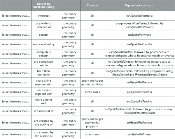
The SpatialRelDescription property is only used when SpatialRel is set to esriSpatialRelRelation. You can use it to define various complex spatial relationships.
The SearchOrder property determines whether the spatial part of the query is performed before the attribute part of the query. By default, the spatial relationship is tested first, but in the case of queries where the attribute criteria are much more specific than the spatial, it is better to change the SearchOrder. An example of this kind of query is "find all worldwide cities with population greater than a million that are not in Spain".
If you want to query a feature class based on a collection of shapes, for example, "select the cities that are within the selected states", you have several options. One option is to apply successive spatial filters for each query shape. Another option is to make a single multipart query shape from the collection of original query shapes, then use a single spatial filter.
The following code example shows how to form a single geometry from the selected features of a feature class:
[C#] // Create a selection set using a spatial filter.
ISelectionSet selectionSet=featureClass.Select(spatialFilter,
esriSelectionType.esriSelectionTypeIDSet,
esriSelectionOption.esriSelectionOptionNormal, null);
// Create a geometry enumerator and bind it to the selection set.
IEnumGeometry enumGeometry=new EnumFeatureGeometryClass();
IEnumGeometryBind enumGeometryBind=(IEnumGeometryBind)enumGeometry;
enumGeometryBind.BindGeometrySource(null, selectionSet);
// Use the GeometryEnvironment class to create a new geometry.
IGeometryFactory geomFactory=new GeometryEnvironmentClass();
IGeometry newGeometry=geomFactory.CreateGeometryFromEnumerator(enumGeometry);
' Create a selection set using a spatial filter.
Dim selectionSet As ISelectionSet=featureClass.Select(spatialFilter, esriSelectionType.esriSelectionTypeIDSet, esriSelectionOption.esriSelectionOptionNormal, Nothing)

' Create a geometry enumerator and bind it to the selection set.
Dim enumGeometry As IEnumGeometry=New EnumFeatureGeometryClass()
Dim enumGeometryBind As IEnumGeometryBind=CType(enumGeometry, IEnumGeometryBind)
enumGeometryBind.BindGeometrySource(Nothing, selectionSet)

' Use the GeometryEnvironment class to create a new geometry.
Dim geomFactory As IGeometryFactory=New GeometryEnvironmentClass()
Dim newGeometry As IGeometry=geomFactory.CreateGeometryFromEnumerator(enumGeometry)
Selections
A SelectionSet object allows an application to reference a selected set of rows all belonging to a single table or feature class. Selection sets are normally used throughout ArcObjects when a temporary subset of rows or features is required for an operation. The selection set only applies to a single table; you cannot sensibly combine two selection sets from different tables.
A selection set can be based on either a set of ObjectIDs that corresponds to the selected rows, or on an actual set of Row objects, instantiated and referenced by the selection set. In either case, the selection set provides methods to iterate over the set of Row objects in the selection. The esriSelectionType property of a selection set, specified by an application at the time that it creates the selection set, determines the type of representation (object IDs or Row object references) used by SelectionSet.
A selection set is typically created from a table or feature class using the Select method on the Table. A query filter is used to specify the subset of rows to include in the selection set as shown in the following code example:
[C#] ISelectionSet selectionSet=featureClass.Select(queryFilter,
esriSelectionType.esriSelectionTypeIDSet,
esriSelectionOption.esriSelectionOptionNormal, null);
Dim selectionSet As ISelectionSet=featureClass.Select(queryFilter, esriSelectionType.esriSelectionTypeIDSet, esriSelectionOption.esriSelectionOptionNormal, Nothing)
An application can create multiple selection sets for a single table or feature class. The selection sets reference their target table, but the datasets have no information about the selection sets that reference them. Applications are responsible for associating the created selection sets with the target table as appropriate. For example, a FeatureLayer in ArcMap holds a reference to a feature class and also to a selection set that it creates on the feature class—at draw time, the selected features are retrieved and drawn in a distinguished manner.
The ISelectionSet interface is used to manage and query the selection set. The Search method is used to iterate over the rows in the selection set and returns a cursor. The Search method takes a query filter that can be used to further restrict the set of rows in the selection that are returned for ID set selections. Using a query filter with hybrid selections forces the representation of the selection to become an ID set selection.
The Select method is used to create a new selection based on a subset of the current selection using a query filter to specify the restriction. The Add, AddList, and RemoveList methods can be used to alter the selection set by adding and removing rows specified by object IDs. The Combine method can be used to combine two selection sets using the standard set operations of union, intersection, difference, and symmetric difference. Only use Combine on two selection sets from the same target—it doesn't make sense to mix lists of IDs from different datasets.
The ISelectionSet2 interface provides an Update method that creates an update cursor on the selection set; this can be used to update and delete rows from the table or feature class of the selection set.
As previously described in this section, the main interface for geodatabase selection sets is ISelectionSet. There are, however, other similarly named interfaces in ArcObjects. The following table summarizes these other interfaces:

QueryDef
A QueryDef object represents a database query on one or more tables or feature classes. QueryDef can be evaluated, resulting in the execution of the query on the database server. The results of the query are returned to the application as a cursor. The application can iterate over the cursor to fetch the Row objects in the result set of the query. The Row objects returned by a cursor on QueryDef are always of type esriGeodatabase.Row—they never have custom behavior or support additional interfaces, even if the table names specified in QueryDef correspond to tables representing ObjectClasses with behavior. The Row objects returned by evaluating QueryDef are read only—these Row objects do not reference a parent table, and the Store method cannot be called on them. Attempting to store a Row object returned by evaluating a QueryDef will result in an error.
The primary use of QueryDef is to directly evaluate database queries on arbitrary tables. It can be used to join tables with the assurance that the join query will execute in the underlying RDBMS. All of the tables in QueryDef must belong to the same workspace (RDBMS). QueryDef can include geometry fields in the specification of the list of fields to be returned but cannot include geometry fields in the where clause specification unless the underlying DBMS is a spatially extended DBMS that supports geometric types, and unless the geometry fields for feature classes are using those native DBMS geometry types for storage.
The IQueryDef interface is used to set up and define the query and provides an Evaluate method that is used to execute the query, returning a cursor. IQueryDef2 provides additional properties, as well as an Evaluate2 method that allows recycling cursors to be returned.
The following code example shows how to create a QueryDef that defines a join between U.S. counties and states:
[C#] // Create a QueryDef and set its properties.
IQueryDef2 queryDef2=(IQueryDef2)featureWorkspace.CreateQueryDef();
queryDef2.Tables="Counties, States";
queryDef2.SubFields="COUNTIES.Shape, COUNTIES.NAME, STATES.STATE_ABBR";
queryDef2.WhereClause="COUNTIES.STATE_FIPS=STATES.STATE_FIPS";
queryDef2.PostfixClause="ORDER BY COUNTIES.NAME";
// Get a recycling cursor by evaluating the QueryDef.
ICursor cursor=queryDef2.Evaluate2(true);
' Create a QueryDef and set its properties.
Dim queryDef2 As IQueryDef2=CType(featureWorkspace.CreateQueryDef(), IQueryDef2)
queryDef2.Tables="Counties, States"
queryDef2.SubFields="COUNTIES.Shape, COUNTIES.NAME, STATES.STATE_ABBR"
queryDef2.WhereClause="COUNTIES.STATE_FIPS=STATES.STATE_FIPS"
queryDef2.PostfixClause="ORDER BY COUNTIES.NAME"

' Get a recycling cursor by evaluating the QueryDef.
Dim cursor As ICursor=queryDef2.Evaluate2(True)
QueryDef objects do not have public constructors. They can only be created from the IFeatureWorkspace interface. This guarantees that all tables in the query are within the same workspace.
The SubFields property is optional when creating QueryDef objects. The default value is "*", which means that all fields are returned.
The OpenFeatureQuery method on a workspace (available in the IFeatureWorkspace interface) can be used to create a FeatureClass that is based on QueryDef. Such a feature class can be added to a map (as a FeatureLayer) and can be used to visually represent the results of a database join query. Such a FeatureClass is similar in concept to an ArcSDE view.
The following code example gets a reference to a feature class based on the QueryDef created in the previous example. The IQueryDef.SubFields property must define one and only one spatial field to create the feature class.
[C#] // Open the feature query as a feature class in a feature dataset.
IFeatureDataset featureDataset=featureWorkspace.OpenFeatureQuery("CountiesStates",
queryDef);
IFeatureClassContainer featureClassContainer=(IFeatureClassContainer)
featureDataset;
IFeatureClass featureClass=null;
if (featureClassContainer.ClassCount == 1)
{
featureClass=featureClassContainer.get_Class(0);
}
' Open the feature query as a feature class in a feature dataset.
Dim featureDataset As IFeatureDataset=featureWorkspace.OpenFeatureQuery("CountiesStates", queryDef)
Dim featureClassContainer As IFeatureClassContainer=CType(featureDataset, IFeatureClassContainer)
Dim featureClass As IFeatureClass=Nothing
If featureClassContainer.ClassCount=1 Then
    featureClass=featureClassContainer.Class(0)
End If
The SQL syntax used with QueryDef objects is the same as that of the underlying database holding the data. An application can use the ISQLSyntax interface on a workspace to determine information about the SQL syntax for the database, such as the delimiter character used in qualifying table and field names and the identifier quote character. QueryDefs represent a subset of the queries that can be made against a SQL database using the SQL SELECT statement. QueryDefs map to simple SQL select statements of the form: SELECT <field names> FROM <list of table names> WHERE <where clause referencing only tables in from list of tables>.
QueryDefs do not guarantee to support SQL statements that do not map to the previously described simple form. In particular, QueryDefs do not guarantee to support nested SELECT statements or correlated subqueries in the WhereClause property, AS keywords embedded in the SubFields property, or the use of table aliases in the Tables property. Support for such capabilities is not guaranteed across all configurations, and applications that rely on such capabilities risk failure.
Relationships
A RelationshipClass object is an association between two object classes; one is the origin class and the other the destination class. The relationship class represents a set of relationships between the objects belonging to two classes. The relationship objects are detailed in the following diagram:
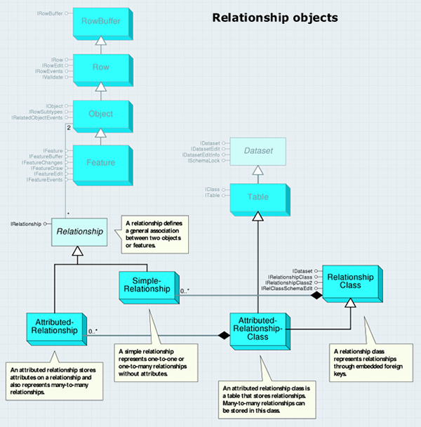
You can create a relationship class with either IRelationshipClassContainer or IFeatureWorkspace. RelationshipClass objects implement IDataset (useful for getting the name or the workspace), but they do not implement IClass (unless they are attributed). This is because a nonattributed relationship class does not have fields of its own.
The IRelationshipClass interface provides information about a relationship class, functionality to create and delete individual relationships, and methods to find related objects. The members of this interface can be split into three logical groups: the properties that correspond to how the relationship class was created, the object-to-object methods that deal with individual relationships, and the relationship rules methods.
The OriginPrimaryKey, OriginForeignKey, DestinationPrimaryKey, and DestinationForeignKey properties can be confusing—their uses are different depending on whether the relationship class is attributed as shown in the following graphic:

The object-to-object methods, such as GetObjectsRelatedToObjectSet, use the ISet interface, which manipulates a set of generic objects. When adding objects to a set with a cursor, make sure that the cursor recycling is disabled, as shown in the following code example (which deletes all the relationships for features with a specific attribute value):
[C#] // Define a filter for which relationships will be deleted.
IQueryFilter queryFilter=new QueryFilterClass();
queryFilter.WhereClause="OWNER='Rusty Shackleford'";
// Create a set of all features satisfying the filter's where clause.
ISet featureSet=new SetClass();
using(ComReleaser comReleaser=new ComReleaser())
{
// Create a cursor and iterate through the features.
IFeatureCursor featureCursor=featureClass.Search(queryFilter, false);
comReleaser.ManageLifetime(featureCursor);
IFeature feature=null;
while ((feature=featureCursor.NextFeature()) != null)
{
featureSet.Add(feature);
}
}
// Delete the relationships for the set's features.
featureSet.Reset();
relationshipClass.DeleteRelationshipsForObjectSet(featureSet);
' Define a filter for which relationships will be deleted.
Dim queryFilter As IQueryFilter=New QueryFilterClass()
queryFilter.WhereClause="OWNER='Rusty Shackleford'"

' Create a set of all features satisfying the filter's where clause.
Dim featureSet As ISet=New SetClass()
Using comReleaser As ComReleaser=New ComReleaser()
' Create a cursor and iterate through the features.
Dim featureCursor As IFeatureCursor=featureClass.Search(queryFilter, False)
comReleaser.ManageLifetime(featureCursor)
Dim feature As IFeature=featureCursor.NextFeature()
While Not feature Is Nothing
    featureSet.Add(feature)
    feature=featureCursor.NextFeature()
End While
End Using

' Delete the relationships for the set's features.
featureSet.Reset()
relationshipClass.DeleteRelationshipsForObjectSet(featureSet)
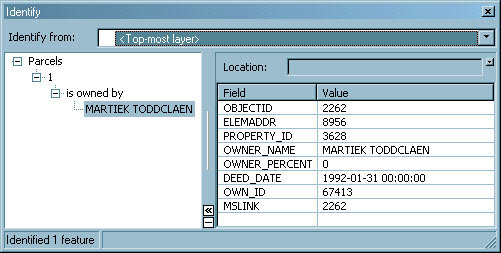
The Identify dialog box in ArcMap allows you to discover objects related to other objects through a relationship class and is shown in the following screen shot:
The CreateRelationship method writes a value into the foreign key field. Consequently, you can overwrite, and thus delete, an existing relationship. Similarly, the DeleteRelationship method removes the foreign key value, so that field must allow null values unless you want to ensure that all objects in the class belong to relationships. The IRelationshipClass2 interface provides a method to get matching objects.
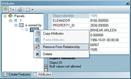
The ArcMap Editor Property Inspector allows you to discover, add, and remove relationships for an object as shown in the following screen shot of the Attributes dialog box:
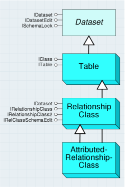
An AttributedRelationshipClass object is a special kind of relationship class and is also a kind of table known as a relationship table. For nonattributed relationship classes, the relationships are stored with the objects themselves in the foreign key values. For attributed relationship classes, the relationships are defined by the objects in conjunction with the rows in the relationship table.
The AttributedRelationshipClass object is shown in the following diagram:
The IRelationshipClass.IsAttributed property only returns true if there are extra relationship attributes beyond those required to relate the objects. The IRelationshipClass.GetRelationship method is useful for accessing the relationship attributes.
A relationship represents a pair of related objects or features. Relationship is an abstract class that covers SimpleRelationship and AttributedRelationship objects. These objects are shown in the following diagram:
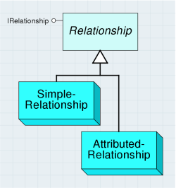
The IRelationship interface provides read-only information about a relationship. It is most useful with attributed relationships since it can form a bridge between the attribute information, which is in row form, and the related objects. When dealing with relationships, you will normally use the IRelationshipClass interface rather than IRelationship.
The SimpleRelationship object represents a pair of related geodatabase objects or features. There are no attribute values associated with SimpleRelationship. Do not cocreate SimpleRelationship. Instead, use IRelationshipClass.CreateRelationship.
The AttributedRelationship object is a kind of row that represents a pair of related objects or features with additional information about the pairing. The additional information is stored in the row.
You cannot create an AttributedRelationship instance through a constructor. Instead, use IRelationshipClass.CreateRelationship. The IRelationshipClassEvents interface provides information as to when two objects are related or unrelated and when attributes on AttributedRelationship are modified. You can use this interface to listen to the OnChange, OnCreate, and OnDelete events on the Relationship class and execute custom behavior based on these events.
Class extension objects
ClassExtension is an object that allows you to customize and extend advanced geodatabase functionality. ClassExtension also allows you to implement optional interfaces to customize geodatabase behavior. ClassExtension can be used to add behavior to ObjectClass or FeatureClass by supporting custom interfaces. The class extension objects are detailed in the following diagram:
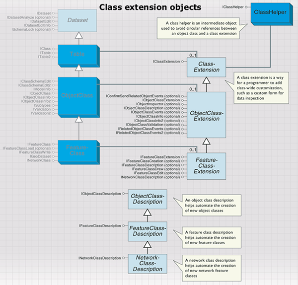
The IClassExtension interface is the main interface required for implementing ClassExtension.
The Init method provides a pointer to the ClassHelper object that should be used to access the extension object’s ObjectClass. ClassExtension should not maintain a reference to ObjectClass directly, but rather should access it via ClassHelper as necessary. In addition to ClassHelper, PropertySet contains any data stored with ObjectClass. The value of PropertySet can be modified by using IClassSchemaEdit.AlterClassExtensionCLSID or IClassSchemaEdit2.AlterClassExtensionProperties. If the properties do not exist for the extension, the pExtensionProperties argument will be Nothing.
The Init method is called when ObjectClass is opened for the first time. Before ObjectClass is closed, the Shutdown method is called. ClassHelper is passed as an argument to the Init method on the IClassExtension interface. ClassHelper is an intermediate object used to prevent circular references between ObjectClass and ClassExtension.
You can optionally implement the following class extension interfaces:
- IObjectInspector—Allows you to replace the ArcMap default Object Inspector with a custom one. Custom object inspectors are easily implemented using a form that implements IObjectInspector.
- IObjectClassValidation—Provides custom validation of objects. This validation is in addition to geodatabase validation of domains, relationship rules, and connectivity rules. After successfully completing all native validation in the geodatabase, the ValidateRow method is called. Effectively, this is the last type of validation performed when validating an object.
- IRelatedObjectClassEvents—Implemented to receive messages about newly created objects in related ObjectClasses.
- IRelatedObjectClassEvents2—Implemented to receive messages about changed and moved objects, either individually or in a set, in related ObjectClasses.
- IConfirmSendRelatedObjectEvents—Used to confirm the messaging of related objects. When an object that participates in a relationship is modified, moved, or rotated (alone or in a set), its related objects will be messaged if relationship notification is set in that direction. Typically, a related object is only involved in certain changes to an object. The properties of this interface allow ObjectClassExtension to prevent or confirm that messages should be sent.
- IObjectClassEvents—Implemented to monitor changes to the objects in ObjectClass. The events on this interface will be called by ObjectClass before notifying other related and external objects. The OnCreate event is called when an object is created. The OnChange event is called when an existing object is modified. The OnDelete event is called when objects in that class are deleted.
- IObjectClassInfo2—Implemented to indicate whether a class required Store to be called when inserting or updating features, even when insert or update cursors are used. This ensures that ObjectClass and RelationshipClass events are broadcast.
- IFeatureClassCreation—Used to specify that new features of this class can be created with a single point. If features can be created from a point, the CanCreateFromPoint property returns true.
- IFeatureClassDraw—Used to specify custom drawing behavior in ArcMap.
- IFeatureClassEdit—Used to specify advanced editing configurations. Implementing this interface allows you to control whether the class can be edited in a spatial reference different from the class. This class extension also allows you to override the default behavior of relationships when a feature in the class is split. When a feature with related objects is split, the geodatabase will automatically maintain or delete the related objects depending on the type of relationship.
The following table of esriRelationshipSplitPolicy enumeration values summarizes how this behavior can be overridden:
|
Enumeration value |
Behavior |
|
esriRSPUseDefault |
The default behavior, which is esriRSPPreserveOnLargest for simple relationships and esriRSPPreserveOnAll for composite relationships. |
|
esriRSPPreserveOnLargest |
Preserve related objects and create a relationship with the feature with the largest part of the split geometry. |
|
esriRSPPreserveOnSmallest |
Preserve related objects and create a relationship with the feature with the smallest part of the split geometry. |
|
esriRSPPreserveOnAll |
Preserve related objects and create a relationship with both features. This option is not valid for relationships with 1:1 cardinality. |
|
esriRSPDeleteRelationship |
Delete the relationship. |
|
esriRSPDeleteParts |
Delete the related objects. |
- ITopologyClassEvents—Provides access to the OnValidate event and fires each time a dirty area is validated in the topology in which the class is participating. The event returns an IGeometry object corresponding to the area that was validated.
Domains and validation rules
The domain and validation rule objects are detailed in the following diagram:
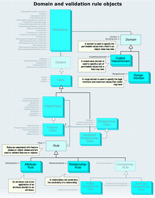
Rules are associated with object classes and are used during the process of validating objects within an object class. The following rule objects are subclassed from the Rule abstract class:
- AttributeRule
- RelationshipRule
- TopologyRule
- ConnectivityRule
Associating a rule with a class does not guarantee that all objects within the class will always be valid; the validation process still needs to be run through the Editor toolbar or with IValidation.Validate. Through the IValidation interface (on the Object class), the set of currently defined rules can be accessed, new rules can be added, and objects can be validated.
IRule is a generic interface that supports validation rules on an object class. Use this interface when you want to determine the type of rule and the helpstring associated with it. Helpstring displays the message associated with the rule. This message is displayed during the process of validating a single feature when that feature is found to be invalid. The helpstring of the first (of possibly many) validation rule that is found to be invalid is displayed through the ArcMap user interface (UI).
Type specifies the type of rule (attribute, relationship, or connectivity) and can be used to determine what validation rule object you are holding. Alternatively, you can probe for the appropriate interfaces (for example, if the rule supports IAttributeRule, then it is an AttributeRule).
The following code extracts the rules for a class and displays basic information about attribute rules:
[C#] // Use the IValidation interface to get the class' rules.
IValidation validation=(IValidation)objectClass;
IEnumRule enumRule=validation.Rules;
enumRule.Reset();
// Iterate through the rules.
IRule rule=null;
while ((rule=enumRule.Next()) != null)
{
if (rule.Type == esriRuleType.esriRTAttribute)
{
IAttributeRule attributeRule=(IAttributeRule)rule;
Console.WriteLine("Field: {0}", attributeRule.FieldName);
Console.WriteLine("Subtype code: {0}", attributeRule.SubtypeCode);
Console.WriteLine("Domain name: {0}", attributeRule.DomainName);
}
}
' Use the IValidation interface to get the class' rules.
Dim validation As IValidation=CType(objectClass, IValidation)
Dim enumRule As IEnumRule=validation.Rules
enumRule.Reset()

' Iterate through the rules.
Dim rule As IRule=enumRule.Next()
While Not rule Is Nothing
    If rule.Type=esriRuleType.esriRTAttribute Then
        Dim attributeRule As IAttributeRule=CType(rule, IAttributeRule)
        Console.WriteLine("Field: {0}", attributeRule.FieldName)
        Console.WriteLine("Subtype code: {0}", attributeRule.SubtypeCode)
        Console.WriteLine("Domain name: {0}", attributeRule.DomainName)
    End If
    rule=enumRule.Next()
End While
Creating a class extension can extend the types of rules that can be defined for an object class. By implementing IObjectClassValidation (along with IClassExtension), any type of custom validation rule can be coded.
Attribute rules and domains
An attribute rule applies an attribute domain to a field of an object class. The AttributeRule class is used to define attribute-specific rules on an object class. This type of rule applies a specified domain to a field name with a specific subtype. Domains can be used to limit the attribute values to a set of valid values or to a range of values. Domains can also define how values in the field are distributed during a split. The process of associating a domain with a field in an object class creates an AttributeRule as a side effect; you generally don't need to explicitly create AttributeRules. The AttributeRule object is shown in the following diagram:
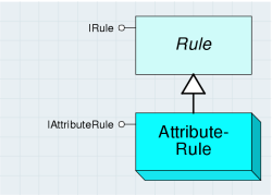
A domain is used to specify the permissible values that a field in an object class can take.
Domain is an abstract class that defines an interface used by the RangeDomain and CodedValueDomain classes to constrain the permissible values that can be associated with a particular field on an object or feature class. Domains can be assigned on a subtype basis, if subtypes exist. The RangeDomain and CodedValueDomain classes are shown in the following diagram:
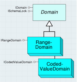
The IDomain interface provides access to the common properties shared across both types of domains. Each property is read-write except the Type property. When creating and assigning a domain to a particular field, the client is required to set the Name and FieldType properties.
A range domain is used to specify the legal minimum and maximum values of a field.
A coded value domain is used to specify a set of permissible values of a field. Domains are used by the ArcMap Property Inspector to constrain the values that you can enter for a field, as well as during the validation process within the geodatabase. A domain can be shared by any number of fields. Domains are associated with a Field object. Domains are added to a dataset at the workspace level through IWorkspaceDomains.AddDomain.
RangeDomains can be associated with fields that are either numeric (such as esriFieldTypeSmallInteger or esriFieldTypeDouble) or date. RangeDomains cannot be associated with string or character fields (esriFieldTypeString).
CodedValueDomains store a set of (value, name) pairs that represent the discrete values that a field can take. The value is what is actually persisted inside a field; the name is what is displayed by the ArcMap Property Inspector. The name can be considered to be a human-readable string that describes what the value represents. In contrast to RangeDomains, CodedValueDomains can also be associated with string fields (esriFieldTypeString); the value can be a string.
The ArcMap Identify dialog box and editor's property inspector use coded value domains to display the human-readable description of values for an attribute. The property inspector also provides a list of valid values for you to select when editing an attribute with a coded value domain, as shown in the following screen shot:
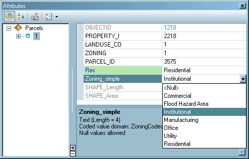
The following code example demonstrates how you can use these properties to display all the (name, value) pairs associated with a coded value domain:
[C#] // Use the ICodedValueDomain interface.
ICodedValueDomain codedValueDomain=(ICodedValueDomain)domain;
// Iterate through the code/value pairs.
for (int i=0; i < codedValueDomain.CodeCount; i++)
{
String name=codedValueDomain.get_Name(i);
object value=codedValueDomain.get_Value(i);
Console.WriteLine("Name: {0}, Value: {1}", name, value);
}
' Use the ICodedValueDomain interface.
Dim codedValueDomain As ICodedValueDomain=CType(domain, ICodedValueDomain)

' Iterate through the code/value pairs.
Dim i As Integer=0
For i=0 To codedValueDomain.CodeCount - 1
    Dim Name As String=codedValueDomain.Name(i)
    Dim Value As Object=codedValueDomain.Value(i)
    Console.WriteLine("Name: {0}, Value: {1}", Name, Value)
Next
Domains are managed at the workspace level. The following screen shot is of the Domains tab of the Database Properties dialog box in the ArcCatalog UI, which is used for creating, deleting, and modifying domains:
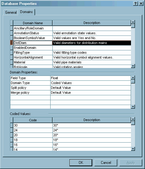
Relationship rules
A RelationshipRule object constrains the cardinality between two subtypes that participate in a RelationshipClass. If the RelationshipClass is a one-to-many relationship, a RelationshipRule may, for example, constrain the cardinality between two subtypes to be one–three. The RelationshipRule cannot conflict with the RelationshipClass. For example, a one-to-many RelationshipClass cannot have any associated relationship rules that constrain the cardinality to be two to two. One RelationshipRule is necessary for each subtype pair that participates in the RelationshipClass. The RelationshipRule object is shown in the following diagram:

The IRelationshipRule interface inherits from IRule. This interface provides access to the various parameters of a relationship rule that are used to refine the cardinalities between subtypes participating in the RelationshipClass. Use this interface when you want to set or retrieve these parameters.
DestinationMaximumCardinality and DestinationMinimumCardinality are only applicable in one-to-many and many-to-many relationships. OriginMaximumCardinality and OriginMinimumCardinality are only applicable in many-to-many relationships.
Connectivity rules
A connectivity rule constrains the type of network connectivity that can be established between edges and junctions in the geometric network. The ConnectivityRule object is shown in the following diagram:
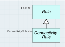
In a geometric network, any edge can connect to any junction. ConnectivityRules are used to constrain the permissible connectivity between edges and junctions. There are two types of connectivity rules that can be applied. JunctionConnectivityRules are placed on junction object classes and determine the valid types of edges that can be connected. EdgeConnectivityRules are placed on edge object classes and determine the valid types of junction or edges (through a junction) that can be connected. Connectivity rules can only be established between network feature classes. The JunctionConnectivityRule object is shown in the following diagram:
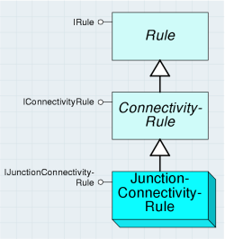
The JunctionConnectivityRule class is a type of ConnectivityRule that constrains the possible valid network connections that can exist between a pair of edge and junction subtypes. It can also constrain the cardinality of the connectivity relationships.
The IJunctionConnectivityRule interface inherits from IConnectivityRule. This interface defines the junction connectivity properties and the valid types of edges that can connect to them. Use this interface to define or manipulate rules between an edge and a junction.
The EdgeConnectivityRule class is a type of ConnectivityRule that defines the permissible relationship between two edge features. In addition, it specifies all the valid junctions that can exist at the connection point between the two edges. It is also possible to specify the default junction that will be placed at the point of connectivity between the two edges. The EdgeConnectivityRule object is shown in the following diagram:
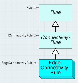
The IEdgeConnectivityRule interface inherits from IConnectivityRule. This interface defines the two types of edges (they can be of the same type) and the valid junctions that can exist between them. DefaultJunctionClassID and DefaultJunctionSubtypeCode define the default junction that will be added at the location where connectivity is established between two edges of the specified type.
The number of junctions associated with EdgeConnectivityRule is unlimited. Junctions are managed through this interface and are accessed on an index basis (the JunctionCount property and the JunctionClassID and JunctionSubtypeCode index-based properties). It is not possible to remove a junction from the rule; if this is required, the rule must be deleted and recreated, less the junction to be deleted.
The following screen shot shows the Connectivity tab on the Geometric Network Properties dialog box of the ArcCatalog UI, which is used for configuring connectivity rules for a geometric network:

Geometric network
A geometric network is a type of graph that is uniquely associated with a logical network, which represents network topology. The geometric network objects are detailed in the following diagram:
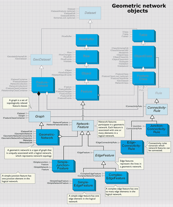
The GeometricNetwork object is responsible for detecting and maintaining network connectivity among a set of feature classes that participate in the network. When new network features are created, GeometricNetwork is responsible for detecting endpoint coincidence (in the case of edge features) with other network features, then communicating with the logical network to establish network connectivity. The GeometricNetwork object is shown in the following diagram:
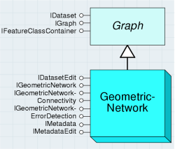
The GeometricNetwork object is also responsible for managing and validating all connectivity rules.
The most common type of third-party client applications that consume the IGeometricNetwork interface are custom network solvers. The associated logical network can be accessed through the Network property. The direct accessibility of the logical network obviates the need to expose the functionality of the logical network through redundant convenience methods at the geometric network level. Functionality that is related to the mapping between geometry (found at the feature level) and network elements (found at the logical network level) is necessarily supported outside the logical network. This is because the logical network does not have an understanding of feature geometry, only logical connectivity.
You can determine the network elements associated with a network feature at a given location through the EdgeElement and JunctionElement properties. If there is more than one network feature of the appropriate type at the location, the edge or junction element that corresponds to the first one encountered is returned.
Complementary functionality is also provided where, for a given edge or junction element, the associated feature geometry is returned via the GeometryForEdgeEID and GeometryForJunctionEID properties, respectively. In contrast to the results returned by the EdgeElement and JunctionElement properties, the GeometryForEdgeEID and GeometryForJunctionEID properties return an unambiguous result, as only one piece of geometry corresponds to a given EID. An EID is an element identification for an element in a logical network.
A method on IGeometricNetwork that can commonly be called by third-party client applications is SearchForNetworkFeature. This method, given a point location and a feature type, returns all the network features that are within the machine precision of this point. If more than one network feature is coincident with the point, then all are returned. The returned network features can span different feature classes; the only restriction is that all features must be of the same feature type.
The IGeometricNetworkErrorDetection interface identifies errors between a geometric network and its logical network. To maintain correct network connectivity in large production environments, it is necessary to have a collection of tools that enable you to detect a variety of connectivity problems within a geometric network. In production environments, it is often impractical to drop the network and rebuild when connectivity problems are encountered during general editing of the network. For this reason, it is necessary to provide a set of tools that enable the end user to detect and repair such problems.
Philosophically, there should be no need for such tools—the network should always be correct. From this standpoint, the geodatabase will not waver. However, the following are circumstances where this may be violated:
- The end user attempts to build a geometric network from data that has illegal geometry.
- Logic errors in the software implementation (as the software matures, this will become less and less likely).
- Applications or tools that do not correctly abort edit operations that the geometric network returns as an error.
- Third-party tools that attempt to manipulate the geometric network at a low level (for example, at the logical network level) and have logic errors in their software implementation.
The CreateErrorTable method creates a table that can be used to persist information related to corrupt network features (using a fixed table schema) with the specified name. Such network error information can only be persisted by the geometric network in a table with this schema. This table is user managed and should remain unversioned.
The DeleteNetworkElements method takes an ISet of ISelectionSet. All the network features contained in the various selection sets will have their network elements deleted from the logical network. The primary reason why you'd want to do this is to correct the geometry of an edge feature that was loaded (prior to ArcGIS 8.1) with corrupt polyline geometry.
If network connectivity errors are found in the geometric network, they can generally be corrected through the use of the RebuildConnectivity method on the IGeometricNetworkConnectivity interface. This method takes an envelope that should contain all the network features for which connectivity should be rebuilt.
A graph is a set of topologically related feature classes. A Graph is an abstract class that factors behavior and attribution common to the different types of topological collections in the geodatabase.
The IGraph interface specifies the attributes and properties expected on all the different types of topological collections in the geodatabase. These attributes and methods are not unique to a particular type of topology. It is not expected that third-party client applications will call many of these methods. The primary clients of the methods on this interface are ArcMap, ArcCatalog, and the polymorphic implementations of the features managed by the graph.
Network features
NetworkFeature is an abstract component that supports network connectivity and participates in a geometric network. The NetworkFeature abstract component is shown in the following diagram:
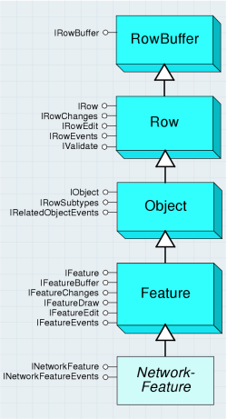
The INetworkFeature interface is supported at the NetworkFeature level in the geodatabase; all features participating in a geometric network support this interface. Because each NetworkFeature can either be enabled (can trace through) or disabled (cannot trace through) in the logical network, the Enabled property is read–write. Although a complex edge can correspond to one or more network elements, setting the Enabled property either enables or disables all associated network elements. It is not possible to individually set the enabled or disabled status of an individual network element associated with a complex network feature through this interface.
When a NetworkFeature is being created and added to a GeometricNetwork coclass, the GeometricNetwork calls the CreateNetworkElements method on the NetworkFeature. It is not necessary for custom feature developers to override this method in their implementation.
If network features are being programmatically created (for example, using a sequence similar to IFeatureClass.CreateFeature, setting the feature’s shape, then calling Store on the feature), the network feature’s spatial reference must match that of the containing FeatureClass. More specifically, if you call IGeometry.Project on the geometry prior to it being set as the feature’s shape, you must ensure that the SpatialReference that is being passed as an argument to the project matches that of the FeatureClass. It is not always the case that the map’s SpatialReference is the correct one to use (for example, if the map contains two FeatureDatasets with differing SpatialReferences).
Junction features are used to maintain network integrity in a geometric network. They are found at the locations that correspond to the endpoints of edge features. They can also be freestanding (unconnected to any edge feature) or connected to complex edges at midspan.
The SimpleJunctionFeature class represents simple junctions on a network that can be added to GeometricNetworks. The SimpleJunctionFeature object is shown in the following diagram:
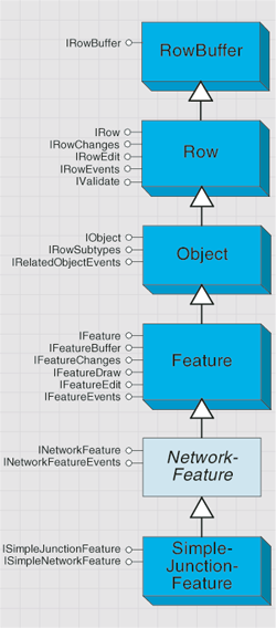
The SimpleJunctionFeature class can be aggregated, and possibly overridden, by custom feature developers.
Simple junction features have point geometry and can be connected to any number of other edge features. A simple junction feature cannot be directly connected to another junction feature without an intervening edge feature.
The ISimpleJunctionFeature interface contains the following properties that are unique to simple junctions:
The EdgeFeatureCount property and EdgeFeature property array are used to specify the connected edge features to the client. The index for EdgeFeature is zero based.
The following code example shows how a client can use this information to display the object IDs of the connected edge features:
[C#] // Use the ISimpleJunctionFeature interface.
ISimpleJunctionFeature simpleJuncFeature=(ISimpleJunctionFeature)junctionFeature;
for (int i=0; i < simpleJuncFeature.EdgeFeatureCount; i++)
{
// Display the edge feature's Object ID.
IEdgeFeature edgeFeature=simpleJuncFeature.get_EdgeFeature(i);
IRow row=(IRow)edgeFeature;
Console.WriteLine("Edge feature [{0}] OID={1}", i, row.OID);
}
' Use the ISimpleJunctionFeature interface.
Dim simpleJuncFeature As ISimpleJunctionFeature=CType(junctionFeature, ISimpleJunctionFeature)
Dim i As Integer=0
For i=0 To simpleJuncFeature.EdgeFeatureCount - 1
    ' Display the edge feature's Object ID.
    Dim edgeFeature As IEdgeFeature=simpleJuncFeature.EdgeFeature(i)
    Dim row As IRow=CType(edgeFeature, IRow)
    Console.WriteLine("Edge feature [{0}] OID={1}", i, row.OID)
Next
Edge features correspond to features with polyline geometry that are part of the network topology within a geometric network. They have two or more connected junction features—one at each location corresponding to the endpoints of their polyline geometries. Complex edges can also have any number of connected midspan junction features. EdgeFeature is an abstract class and is shown in the following diagram:
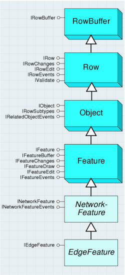
The IEdgeFeature interface must be supported by both simple and complex edges. This interface is found on the EdgeFeature abstract class. The various properties on this interface facilitate network feature navigation for client applications.
The FromToJunctionEIDs property hands back both the FROM and TO junction EIDs; it is more efficient to access this property than to call FromJunctionEID and ToJunctionEID. These properties are generally computationally expensive. For certain clients (that is, those that do not require access to the geometry, attributes, or feature class associated with the network feature), it can be more advantageous to directly utilize the logical network when performing navigation between large numbers of network features. For example, with network solvers.
The Update method is reserved for internal consumption (during the process of updating the shape and storing the result); there is no need for clients to call this method directly.
Simple edge features correspond to features with polyline geometry that are part of the network topology within a geometric network. They have two connected junction features—one at each location corresponding to the endpoints of their polyline geometries. Junction features connected at midspan are not allowed. If you attempt to connect a junction at midspan on a simple edge feature, a split operation occurs. (The original simple edge feature is deleted and replaced by two new simple edge features that are commonly connected at the junction feature that caused the subdivision.)
The SimpleEdgeFeature class is shown in the following diagram:
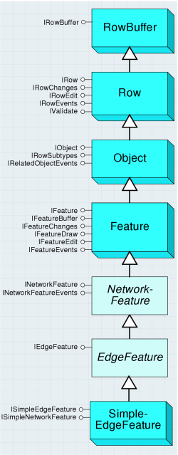
Complex edge features correspond to features with polyline geometry that are part of the network topology within a geometric network. They have two or more connected junction features—one at each location corresponding to the endpoints of their polyline geometries. They can also have any number of connected midspan junction features. The ComplexEdgeFeature class is shown in the following diagram:

Connecting a junction feature to a ComplexEdgeFeature does not result in a physical subdivision of the edge; instead, it results in a logical subdivision (that is, new edge elements in the logical network that are associated with the complex edge).
The geometry of ComplexEdgeFeatures may not be self-intersecting; there may be discontinuities with the geometry (they may be multipart), and the geometry may not have the same start and stop vertex (that is, a closed loop).
Simple edge features are connected to exactly two junction features, while complex edges can be connected to two or more junction features as shown in the following graphic:
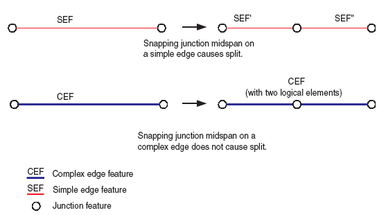
The IComplexEdgeFeature interface is supported on ComplexEdgeFeature. The GeometryForEID property allows clients to obtain the portion of the complex edge’s geometry that corresponds to a specified EID. This is useful for network solvers in particular. The JunctionFeature property array is a mechanism for clients to obtain all the junction features that are associated with the complex edge.
For further information see:
Adding and working with connectivity rules in a geometric networkCreating geometric networks within a geodatabase
Topology
A topology is a collection of simple feature classes in the same feature dataset that participate in topological relationships with a set of rules that govern those relationships. Topologies can have multiple feature classes in the same topological role. A feature dataset can have multiple topologies, but a feature class can only belong to one topology. Each topology has one associated topology graph. The topology graph is a planar representation of the geometries in the feature classes participating in a geodatabase topology.
The topology objects are detailed in the following diagram:
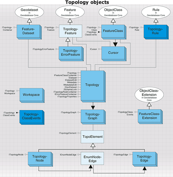
The Topology object is shown in the following diagram:
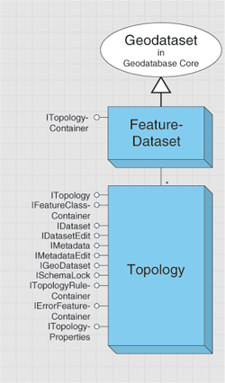
The Topology class does not have a public constructor; topologies must be created through ITopologyContainer.CreateTopology.
The ITopology interface provides properties of a topology and methods for adding feature classes and validating dirty areas.
When new features are created, edited, or deleted, the topology is responsible for creating or modifying a dirty area that will encompass the envelope of the feature as shown in the following graphic. A dirty area is a special type of feature under which the state of the topology is unknown.
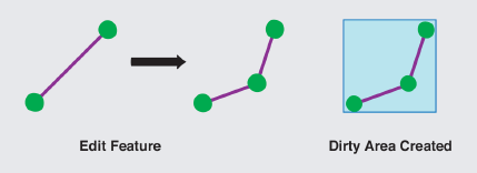
Features that are covered by dirty areas can still be edited and queried, but their topological relationships cannot be guaranteed to be correct. A dirty area must be validated in order to discover the topology of its underlying features.
The following code shows how to obtain a reference to a topology in your feature workspace:
[C#] IFeatureDataset featureDataset=featureWorkspace.OpenFeatureDataset("Landbase");
ITopologyContainer topologyContainer=(ITopologyContainer)featureDataset;
ITopology topology=topologyContainer.get_TopologyByName("Landbase_Topology");
Dim featureDataset As IFeatureDataset=featureWorkspace.OpenFeatureDataset("Landbase")
Dim topologyContainer As ITopologyContainer=CType(featureDataset, ITopologyContainer)
Dim topology As ITopology=topologyContainer.TopologyByName("Landbase_Topology")
The AddClass method is used to add a feature class to the topology, with the specified weight and ranks.
Non-simple feature classes, such as annotation, dimension, and geometric network feature classes, cannot be added to a topology. Object classes or tables and versioned simple feature classes cannot be added to a topology. After a populated feature class is added to a topology that has already been validated, in whole or in part, the state of the topology is changed, and a dirty area corresponding to the extent of the feature class is created. If an unpopulated feature class is added to a topology, the topology’s state does not change and no dirty area is created. The AddClass method cannot be called on versioned topologies in ArcSDE but can be called on non-versioned topologies in ArcSDE and topologies in a personal geodatabase.
Topologies support the IFeatureClassContainer interface, which can be used to return the feature classes participating in the topology.
The Cache property returns a reference to the topology graph of the topology. The topology graph can be used to work with topological primitives, such as edges and nodes.
The ClusterTolerance property returns the tolerance that was specified when the topology was built. The ClusterTolerance of the topology cannot be changed. To modify the tolerance, the topology must be deleted and rebuilt with the new ClusterTolerance.
The DirtyArea property returns the dirty area polygon of the topology. The DirtyArea property requires an IPolygon object as input. IPolygon can correspond to the extent of the topology or a subset of the extent. If there is no dirty area intersecting the specified area, an empty polygon is returned. The dirty area polygon that is returned can be a multipart polygon.
The following code example demonstrates how to obtain the dirty area for the entire topology:
[C#] // Use the IGeoDataset interface to get the topology's extent.
IGeoDataset geoDataset=(IGeoDataset)topology;
IPolygon searchArea=new PolygonClass();
ISegmentCollection segmentCollection=(ISegmentCollection)searchArea;
segmentCollection.SetRectangle(geoDataset.Extent);
// Check the entire topology for the dirty area.
IPolygon dirtyArea=topology.get_DirtyArea(searchArea);
' Use the IGeoDataset interface to get the topology's extent.
Dim geoDataset As IGeoDataset=CType(topology, IGeoDataset)
Dim searchArea As IPolygon=New PolygonClass()
Dim segmentCollection As ISegmentCollection=CType(searchArea, ISegmentCollection)
segmentCollection.SetRectangle(geoDataset.Extent)

' Check the entire topology for the dirty area.
Dim dirtyArea As IPolygon=topology.DirtyArea(searchArea)
Topology errors and validation
Each topology has a maximum number of errors that can be generated on Validate, which can be determined through the MaximumGeneratedErrorCount property. MaximumGeneratedErrorCount can only be specified when a topology is created programmatically. All topologies created with the New Topology wizard in ArcCatalog have a MaximumGeneratedErrorCount of –1, indicating no limit to the number of errors that can be generated. As with the ClusterTolerance property, the MaximumGeneratedErrorCount property cannot be changed; a topology must be deleted and rebuilt to specify a new value.
The RemoveClass method removes the specified class from the topology. While RemoveClass removes topology rules and errors associated with the class, it does not result in the creation of a dirty area, nor does the state of the topology change. The State property indicates the current status of the topology; whether the topology has been validated and if so, whether any topology errors have been discovered.
ValidateTopology validates the dirty area of the topology in the area specified by the areaToValidate envelope. ValidateTopology evaluates all the rules and produces any topology errors corresponding to areas in which a rule has been violated. The ValidateTopology method returns the envelope of the validated area. If an empty envelope is supplied, ValidateTopology returns an empty validated area. ValidateTopology can be performed outside an edit session on topologies in personal geodatabases or on topologies in ArcSDE geodatabases that have not been registered as versioned. Once a topology is registered as versioned, ValidateTopology must be performed in an edit session and bracketed in an edit operation. The IWorkspaceEdit or IEditor interfaces can be used to manage edit sessions and edit operations.
An entire topology can be validated by supplying the envelope of the extent of the topology as shown in the following code example:
[C#] // Validate the entire topology.
IGeoDataset geoDataset=(IGeoDataset)topology;
IEnvelope extent=geoDataset.Extent;
topology.ValidateTopology(extent);
' Validate the entire topology.
Dim geoDataset As IGeoDataset=CType(topology, IGeoDataset)
Dim extent As IEnvelope=geoDataset.Extent
topology.ValidateTopology(extent)
By supplying a polygon object to the ITopology.DirtyArea property, the dirty area at a particular location can be returned. The envelope of the returned dirty area polygon can then be passed to ValidateTopology as shown in the following code example:
[C#] // Use the IGeoDataset interface to get the topology's extent.
IGeoDataset geoDataset=(IGeoDataset)topology;
IPolygon searchArea=new PolygonClass();
ISegmentCollection segmentCollection=(ISegmentCollection)searchArea;
segmentCollection.SetRectangle(geoDataset.Extent);
// Check the entire topology for the dirty area.
IPolygon dirtyArea=topology.get_DirtyArea(searchArea);
// Validate the topology based on the dirty area's envelope.
IEnvelope dirtyAreaEnvelope=dirtyArea.Envelope;
topology.ValidateTopology(dirtyAreaEnvelope);
' Use the IGeoDataset interface to get the topology's extent.
Dim geoDataset As IGeoDataset=CType(topology, IGeoDataset)
Dim searchArea As IPolygon=New PolygonClass()
Dim segmentCollection As ISegmentCollection=CType(searchArea, ISegmentCollection)
segmentCollection.SetRectangle(geoDataset.Extent)

' Check the entire topology for the dirty area.
Dim dirtyArea As IPolygon=topology.DirtyArea(searchArea)

' Validate the topology based on the dirty area's envelope.
Dim dirtyAreaEnvelope As IEnvelope=dirtyArea.Envelope
topology.ValidateTopology(dirtyAreaEnvelope)
Topology rules
The ITopologyRuleContainer interface provides access to members for adding, removing, and returning topology rules from a topology. This interface also provides access to members that control the promotion and demotion of topology errors and exceptions.
The CanAddRule property returns a Boolean value indicating if the topology rule is valid with respect to the existing rules. This property will return false under the following scenarios:
- An identical rule is already present in the topology.
- A topology rule of the same rule type with the same origin and destination feature class is already present in the topology, but the rule being added is defined at the subtype level.
- The topology rule has been specified to use subtypes; however, subtypes are defined for the relevant feature class.
The AddRule method is used for adding a new rule to a topology. The addition of the new rule results in a dirty area created for the extent of the entire topology and a change to the state of the topology to esriTSUnanalyzed. The DeleteRule method removes the specified rule from the topology, resulting in a dirty area created for the extent of the entire topology and a change to the state of the topology to esriTSUnanalyzed.
The DemoteFromRuleException method demotes the specified exception from being an exception to an error feature. On a topology in an ArcSDE geodatabase, DemoteFromRuleException must be called from within an edit session and edit operation. The PromoteToRuleException method promotes an error feature from an error to an exception. On a topology in an ArcSDE geodatabase, PromoteToRuleException must be called from within an edit session and edit operation.
When you validate a topology, features that violate the rules are marked as error features. You can edit the features to fix the errors, or you can mark the errors as exceptions. In the following graphic, the street line features cannot have dangles, which are endpoints that do not connect to other street features. Because cul-de-sac streets are a legitimate exception to this rule, they can be marked as exceptions in the topology. The remaining errors should be fixed by editing the street features.

The ITopologyClass interface provides read-only access to the properties of feature classes in a topology. Most of these properties are specified when the feature class is added to the topology.
The ITopologyContainer interface can be used to create and manage topologies in a feature dataset. To simply browse for the set of topologies in a feature dataset, it is not necessary to open the feature dataset and call the methods on ITopologyContainer. The IFeatureDatasetName2.TopologyNames property can be used to efficiently obtain this information. Consideration should be given to specifying the parameters when creating a topology. Once the topology is built, none of the parameters can be modified. To change properties such as cluster tolerance, the topology must be deleted and rebuilt with the new parameters.
The ITopologyProperties interface provides access to additional properties of a topology not supplied through the ITopology interface, such as the enumeration of feature classes and spatial reference of the topology.
The ITopologyWorkspace interface provides access to the OpenTopology method that allows you to open a topology in a workspace given the topology’s name. Use this interface to open a topology when you only have a reference to a workspace object. For ArcSDE geodatabases, the fully qualified name can be used to return topologies owned by specific users. If multiple topologies with the same name and owned by different users exist within the geodatabase, OpenTopology will return the topology owned by the connected user if an unqualified name is supplied.
The ITopologyErrorFeature interface provides access to the read-only properties of topology error features. Topology error features represent violations of topology rules and are discovered during the validation process. Error features cannot be edited directly, so while you can cast for interfaces such as IFeature on a TopoloyErrorFeature, calling methods such as IFeature.Value or IFeature.Store will fail. The only modification that can be made to a topology error feature is to mark it as an exception using ITopologyRuleContainer.PromoteToRuleException. Conversely, an exception can be marked as an error by passing it as an argument to ITopologyRuleContainer.DemoteFromRuleException.
The OriginClassID and DestinationClassID properties represent the object class IDs of the origin and destination feature classes of the topology rule of which the error feature is a violation. The OriginOID and DestinationOID properties represent the object IDs of the origin and destination features that created the topology error.
In general, all topology errors for which only the origin class has been specified will return values for the OriginClassID and OriginOID properties and a value of zero for the DestinationClassID and DestinationOID properties. The exception is for topology errors generated from the esriTRTNoGaps rule, which will return a value of zero for the Origin as well as Destination ID and OID properties. In addition, topology rules whose origin and destination feature class have been specified will generally return zero for the Destination feature class properties. The exceptions to this rule are located in esriTopologyRuleType constants and are as follows:
- esriTRTAreaNoOverlap
- esriTRTAreaNoOverlapArea
- esriTRTLineNoOverlap
- esriTRTLineNoIntersection
- esriTRTLineNoOverlapLine
- esriTRTLineNoIntersectOrInteriorTouch
The exception to both of these statements is the esriTRTAreaAreaCoverEachOther rule, which can generate topology errors referencing either the Origin or Destination feature class.
The ErrorID of a topology error feature is not unique across all topology error features within the topology but is unique for each topology error feature geometry type. While a topology error feature with polygon geometry can have the same ErrorID as a topology error feature with point geometry, the ErrorID will be unique for all topology error features with polygon geometry. Combining the ErrorID and ShapeType of a topology error feature results in a unique value within the topology.
The TopologyRule class defines the permissible spatial relationships between features in a topology. Topology rules can be defined with a single feature class or between two feature classes. Topology rules can also be defined to the subtype level of a feature class. Topology rules have an origin and a destination feature class, either of which can be set to the subtype level. Depending on the type of topology rule that is implemented, the destination feature class properties may be irrelevant. The Topology Rule object is shown in the following diagram:
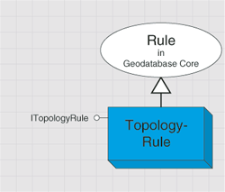
ITopologyRule is the main interface for creating and returning information about a topology rule. Use this interface to create a topology rule or return the properties of an existing rule.
The AllDestinationSubtypes property specifies if the rule applies to all subtypes in the destination feature class. By default, AllDestinationSubtypes is false and the DestinationSubtype property points to the default subtype. If AllDestinationSubtypes is explicitly set to false, the DestinationSubtype property must be set or the rule will be invalid. AllDestinationSubtypes returns the opposite value of the DestinationSubtypeSpecified property. If the topology rule is a single feature class rule, AllDestinationSubtypes is set to true once the rule is added to the Topology.
AllOriginSubtypes specifies if the rule applies to all subtypes in the origin feature class. By default, AllOriginSubtypes is false and the OriginSubtype property points to the default subtype. If AllOriginSubtypes is explicitly set to false, the OriginSubtype property must be set or the rule will be invalid. AllOriginSubtypes returns the opposite value of the OriginSubtypeSpecified property.
The DestinationClassID property corresponds to the ObjectClassID of the destination feature class of the topology rule. If the topology rule is a single feature class rule, the DestinationClassID property does not need to be set, it will be equal to the OriginClassID property by default and if set, will be ignored when the rule is added to the topology. The OriginClassID property corresponds to the ObjectClassID of the origin feature class of the topology rule. Every topology rule will have an OriginClassID.
OriginSubtype and DestinationSubtype correspond to the origin and destination subtypes of the topology rule. Setting the OriginSubtype or DestinationSubtype will result in the corresponding OriginSubtypeSpecified or DestinationSubtypeSpecified property returning true. If AllOriginSubtypes or AllDestinationSubtypes is set to true, the value specified for OriginSubtype or DestinationSubtype will be ignored. The ErrorShapeTypes method indicates the error shape types that can be produced by the topology rule. If the rule supports a particular shape type, it will return a value of true.
The GUID property is read only and returns the unique, geodatabase-controlled value that is set when the rule is added to the topology using ITopologyRuleContainer.AddRule. The GUID value can be used to return its associated topology rule using ITopologyRuleContainer.RuleByGUID. The Name property can be used to assign a user-specified string to each rule. By default, the Name property is empty.
The TopologyRuleType property is used to return or set the type of topology rule from the esriTopologyRuleType constants. Every topology has one inherent rule, the esriTRTFeatureLargerThanClusterTolerance rule, which is added implicitly when the topology is created.
The rules you define for a topology control the allowable relationships of features within a feature class, between features in different feature classes, or between subtypes of features. The following illustration shows a "must not overlap" rule applied to polygons and lines. The red polygon and line mark the places where the rule is violated. These are stored in the topology as error features. Such rules can apply to features within the same feature class, to pairs of feature classes, or to subtypes of features.

Topology graph
As mentioned previously, the Cache property on ITopology returns a reference to the topology graph of the topology. The topology graph can be used to work with topological primitives such as edges and nodes.
A topology graph is a cached planar representation of the feature geometries participating in a topology, where the topological relationships are known. There is only one graph per topology. It is derived from the Topology object and cannot be cocreated. The TopologyGraph object allows editing of a topology without breaking adjacency or connectivity of the participating features, also known as "shared editing". For example, TopologyGraph can be used to edit the shared boundaries of two polygons without breaking the adjacency of their geometries. Additionally, you can use it to move a set of overlapping routes while keeping all features coincident. There are a number of properties and methods that can be used on the TopologyGraph object and its components to accomplish the following:
- Navigate through it
- Modify the geometry of the topology elements
- Discover the relationship between features
- Modify the connectivity between features
A TopologyGraph object is accessed from a Topology object and is constructed for a given extent. It references the topology primitives that are cached. The topology primitive geometries present in memory have been modified, via cracking and clustering, during a round trip to the topology engine. However, these geometries are not yet updated on disk. They are updated only if the topology elements are modified and those edits are posted back to disk. For example, you can programmatically move a topology node that is shared by several features. This edit is cached in memory until the ITopologyGraph.Post method is called. That method propagates the edit to all the features sharing that topology node; the geometries of those features are then updated.
The TopologyGraph object is a singleton object. The topology graph is empty initially and must be built to contain the topology primitives.
For a given topology, the topology graph is built on demand with a user-defined envelope bounding its included features. At construction time, the feature geometries are sent to the topology engine where they are cracked and clustered using the cluster tolerance for the topology. Cracking and clustering is a process where vertices are introduced at each feature intersection and the new and existing vertices are grouped into clusters. This process is necessary to remove ambiguities between features and to discover their topological relationships. After cracking and clustering, the features are, at minimum, separated by the cluster tolerance of the given topology. For a second time, the topological relationships between features are discovered and sent back to the client code. The topology primitives (geometry and topological relationships) are persisted in memory for further use.
The TopologyGraph architecture is shown in the following diagram:
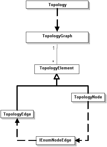
There are two types of topology primitives, or elements, that are cached—nodes and edges. TopologyNode is an object holding a reference to an IPoint geometry. It is created at each feature's endpoints as well as at the intersections of feature geometries participating in the topology. The node also contains topological relationship information, such as incident TopologyEdges and corresponding TopologyParents. A TopologyParent is a pointer to a feature class coupled with a feature object identifier (OID). This couple uniquely identifies a feature part of the topology.
TopologyEdge is defined as an object holding a reference to an IPolyline geometry (always single part) formed between two TopologyNodes. The edge also references the topological relationship information, such as FromTopologyNode, ToTopologyNode, and TopologyParents. TopologyEdge also allows its left and right polygons to be identified when appropriate. The relationship between nodes, edges, and features can be accessed at any time using the TopologyGraph API. The following two diagrams give representations of the TopologyGraph object.
In the first diagram, two polyline features are used to construct the topology graph. The TopologyGraph is persisted in memory and contains nine topology primitives: five nodes and four edges. Each TopologyNode knows which features were used to construct it; those features are called TopologyParents. For example, the parents of the center TopologyNode are the two polyline features. The TopologyNode also knows which TopologyEdges are connected to it. The edges, in turn, are aware of their TopologyParents, as well as the FromTopologyNode and the ToTopologyNode.
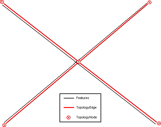
In the second diagram, a polyline feature overlaps the boundaries of two adjacent polygon features. In this case, the TopologyGraph contains five topology primitives: two nodes and three edges. Each TopologyNode has three TopologyParents—the polyline and both polygons. The black arrow shows the orientation of the polyline feature. The red arrows show the orientation of the TopologyEdges. For example, the central TopologyEdge has three parents, the polyline and both polygons. Using this TopologyEdge and the ITopologyEdge.LeftParents or ITopologyEdge.RightParents property, you can access the blue and green polygons. The orientation of the edge determines which polygon is the left or right parent. A TopologyEdge also knows which TopologyNodes are associated with it. You can use this information to navigate in the TopologyGraph. A topology element can have 1-N TopologyParents. The parents are the features that share geometries at a given location.
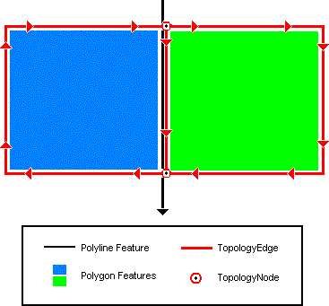
The ITopologyGraph interface exposes several methods for interacting with the elements of a topology and, therefore, the underlying features participating in the topology. You can access all or selected elements of a TopologyGraph as follows:
- All elements—Use the ITopologyGraph.Edges or ITopologyGraph.Nodes property.
- The selected element—Use ITopologyGraph.EdgeSelection or ITopologyGraph.NodeSelection.
- Elements associated with a specific feature—Use the ITopologyGraph.GetParentEdges or ITopologyGraph.GetParentNodes method. You must have a pointer to the feature before using either of these methods.
- Elements using a geometry—Use the ITopologyGraph.HitTest or ITopologyGraph.SelectByGeometry method. This allows you to locate an element based on a user’s click or other geometry.
Once you’ve accessed the topology elements, you can work with their associated topological relationships. To retrieve specific relationships, use the following properties:
- FromTopologyNode and ToTopologyNode associated with an edge—Use the ITopologyEdge.FromNode or ITopologyEdge.ToNode property.
- The set of edges incident to a TopologyNode—use the ITopologyNode.Edges property. The edges can be returned in clockwise or counterclockwise order.
As discussed earlier, the features associated with a topology element are known as its TopologyParents. Access to TopologyParents is available as follows:
- All parents associated with either an edge or a node—Use the ITopologyElement.Parents property.
- The left and right parent of an edge—Use the ITopologyEdge.LeftParents and ITopologyEdge.RightParents properties.
Topology elements can be moved or transformed in a variety of ways. The methods used vary according to the type of transformation and are described as follows:
- Moving topology elements while respecting geometric relationships—Use the ITopologyGraph.TransformSelection method. The topology elements can be transformed using any supported transformation type, from the simple translation to the affine transformation.
- Moving topology elements without respecting geometric relationships—Use ITopologyGraph.SplitMoveNode. This modifies the elements of a topology in a way that may break the existing topology relationships (connectivity and adjacency). This operation is only successful if a valid topology relationship is recreated. For example, the operation will be aborted if a polygon becomes degenerated during SplitMoveNode.
- Changing the shape of a TopologyEdge geometry—The ITopologyGraph.ReshapeEdgeGeometry method can be used to modify the geometry of the edge based on another geometry. For example, this method is used by the Reshape Edge Task in the editor.
- Replacing the geometry of TopologyEdge—ITopologyGraph.SetEdgeGeometry replaces the current geometry of TopologyEdge with the input geometry. For example, this method is used by the Modify Edge task in the editor. This method does not allow the modification of TopologyEdge endpoints.
By default, any operation done on the TopologyGraph affects all TopologyParents (features) associated with its edited elements. However, you can control which features are affected by a given operation. The TopologyParent selection (used by the Show Shared Features dialog box on the Topology toolbar in ArcMap) can help modify this behavior. The parent selection is defined as the state of the TopologyParents for a given operation. This state, by default, is set to true for all TopologyParents. By changing this state to false, some features can be subtracted from the subsequent TopologyGraph operation. This can be done using the ITopologyGraph.SetParentSelected method. The state is reset to its default after any TopologyGraph operation.
Modifying a TopologyGraph element does not immediately modify the features on disk. A topology edit exists in memory but the features are not modified until the ITopologyGraph.Post method is called. This method propagates the edits made on the topology element’s geometry into the features associated with it (TopologyParents). In basic terms, it replaces the edited feature’s geometry with the geometries that went to the topology engine and have the modified shape.
Since all topology primitives are stored in memory, building the TopologyGraph for a large extent is not recommended. For efficiency reasons, the smaller the extent of the TopologyGraph, the better; however, some applications might require larger extents. As an alternative, it is possible to build several smaller TopologyGraphs in some cases. The amount of random access memory (RAM) available on your computer is directly correlated to the performance of the TopologyGraph: the more RAM, the better.
Data elements
In general, data elements describe entities that can be used in geoprocessing functions. Examples of such classes are DEFolder, DETable, and DEShapeFile. These objects are simple structures whose properties describe the actual entity. For example, DEShapeFile has properties such as extent and spatial reference. A subset of the data elements describes geodatabase datasets. The classes DEFeatureClass, DEFeatureDataset, and others can be used to describe actual geodatabase datasets.
The data element objects are detailed in the following diagram:
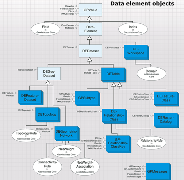
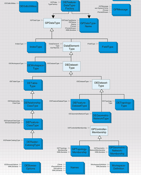
The workspace and feature dataset are containers of other datasets. Likewise, DEWorkspace and DEFeatureDataset will contain other data elements in the Children property (accessible through the IDataElement interface).
Data elements support IXMLSerialize and IPersistStream; thus, a set of data elements can be serialized in Extensible Markup Language (XML) or binary form.
Data elements can be created in several ways. Data elements are cocreatable, and application developers can create new instances of a data element then fill its properties with appropriate values. In ArcCatalog, the data element associated with GxObject can be obtained by using the GetDataElement method in the IGxDataElement interface. A workspace can implement the IWorkspaceDataElements interface, which can be used to request a data element for the whole workspace, or a data element for a particular dataset.
The CatalogPath of a data element contains the path to the dataset. If retrieved from GxObject, the data element's catalog path will correspond to the path displayed by ArcCatalog when the dataset is selected in the view pane. If retrieved from the workspace, the catalog path will be built by following this pattern:
/V=[version]/DatasetKeyword=datasetName/ChildDatasetKeyword=datasetName
where the path elements are separated using a slash character and the dataset keywords are taken from the following list. The version can be empty if the source is a personal geodatabase.
The following table shows the dataset types and their respective keywords:
|
Dataset type |
Keyword |
| Feature dataset | FD |
| Feature class | FC |
| Object class | OC |
| Relationship class | RC |
| Geometric network | GN |
| Topology | TOPO |
| Raster band | RB |
| Raster dataset | RD |
| Raster catalog | RCAT |
| Toolbox | TB |
The following are sample catalog paths:
- /V=/FD=USA/FC=Capitals
- /V=SDE.DEFAULT/FD=Landbase/FC=Parcels
The GetDatasetDataElement method in IWorkspaceDataElements allows client code to create a data element from a name object or from a dataset object as shown in the following code example. In the first case, only the properties available in the name object will be populated in the resulting data element. The Boolean RetrieveFullProperties property in IDEBrowseOptions must be set to false when using a name object as input.
[C#] // Get a name object for the first feature class in the workspace.
IEnumDatasetName enumDatasetName=workspace.get_DatasetNames
(esriDatasetType.esriDTFeatureClass);
enumDatasetName.Reset();
IDatasetName datasetName=enumDatasetName.Next();
// Create a DEBrowseOptions object to define how the data element is populated.
IDEBrowseOptions deBrowseOptions=new DEBrowseOptionsClass
{
RetrieveFullProperties=false, ExpandType=esriDEExpandType.esriDEExpandNone
};
// Generate a data element for the feature class.
IWorkspaceDataElements workspaceDataElements=(IWorkspaceDataElements)workspace;
IDataElement dataElement=workspaceDataElements.GetDatasetDataElement(datasetName,
deBrowseOptions);
' Get a name object for the first feature class in the workspace.
Dim enumDatasetName As IEnumDatasetName=workspace.DatasetNames(esriDatasetType.esriDTFeatureClass)
enumDatasetName.Reset()
Dim datasetName As IDatasetName=enumDatasetName.Next()

' Create a DEBrowseOptions object to define how the data element is populated.
Dim deBrowseOptions As IDEBrowseOptions=New DEBrowseOptionsClass With _
                                          { _
                                          .RetrieveFullProperties=False, _
                                          .ExpandType=esriDEExpandType.esriDEExpandNone _
                                          }

' Generate a data element for the feature class.
Dim workspaceDataElements As IWorkspaceDataElements=CType(workspace, IWorkspaceDataElements)
Dim dataElement As IDataElement=workspaceDataElements.GetDatasetDataElement(datasetName, deBrowseOptions)
When using a dataset as input, the GetDatasetDataElement method returns a fully populated data element as shown in the following code example:
[C#] // Open a feature class.
IFeatureClass featureClass=featureWorkspace.OpenFeatureClass("Parcels");
// Create a DEBrowseOptions object to define how the data element is populated.
IDEBrowseOptions deBrowseOptions=new DEBrowseOptionsClass
{
RetrieveFullProperties=true, ExpandType=esriDEExpandType.esriDEExpandNone
};
// Generate a data element for the feature class.
IWorkspaceDataElements workspaceDataElements=(IWorkspaceDataElements)workspace;
IDataElement dataElement=workspaceDataElements.GetDatasetDataElement(featureClass,
deBrowseOptions);
' Open a feature class.
Dim featureClass As IFeatureClass=featureWorkspace.OpenFeatureClass("Parcels")

' Create a DEBrowseOptions object to define how the data element is populated.
Dim deBrowseOptions As IDEBrowseOptions=New DEBrowseOptionsClass With _
                                          { _
                                          .RetrieveFullProperties=True, _
                                          .ExpandType=esriDEExpandType.esriDEExpandNone _
                                          }

' Generate a data element for the feature class.
Dim workspaceDataElements As IWorkspaceDataElements=CType(workspace, IWorkspaceDataElements)
Dim dataElement As IDataElement=workspaceDataElements.GetDatasetDataElement(featureClass, deBrowseOptions)
The ExpandType property of DEBrowseOptions controls whether data elements are created for children of the requested data element. Client code can request immediate children only or all descendants. For example, when using the GetWorkspaceDataElement method with immediate children, data elements for tables, feature datasets, and other datasets at the workspace level will be created, but no data element will be created for datasets under the feature datasets. The dataset's metadata will be retrieved only if RetrieveMetadata is set to true.
The GdbSchemaCreator class can be used to create the schema given an array of data elements. It requires the data elements to be populated with their full properties to create the datasets.
In the following code example, a feature class is created in one workspace by creating a data element for an existing feature class in another workspace. This code is somewhat simplified for brevity; it makes the assumption that no domains are used in the feature class, and it also assumes that the new feature class will not conflict with an existing feature class.
[C#] // Open a feature class from the source workspace.
IFeatureWorkspace featureWorkspace=(IFeatureWorkspace)sourceWorkspace;
IFeatureClass featureClass=featureWorkspace.OpenFeatureClass("Parcels");
// Create a data element for the feature class.
IWorkspaceDataElements workspaceDataElements=(IWorkspaceDataElements)
sourceWorkspace;
IDEBrowseOptions deBrowseOptions=new DEBrowseOptionsClass
{
ExpandType=esriDEExpandType.esriDEExpandNone, RetrieveFullProperties=true
};
IDataElement dataElement=workspaceDataElements.GetDatasetDataElement(featureClass,
deBrowseOptions);
// Create an array for the data element.
IArray dataElementArray=new ArrayClass();
dataElementArray.Add(dataElement);
// Generate a name mapping enumerator for the target workspace.
IGdbSchemaCreator gdbSchemaCreator=new GdbSchemaCreatorClass();
IEnumNameMapping enumNameMapping=null;
Boolean conflictsFound=false;
gdbSchemaCreator.GenerateNameMapping(targetWorkspace, dataElementArray, null, out
enumNameMapping, out conflictsFound);
enumNameMapping.Reset();
// Create the schema in the target workspace.
gdbSchemaCreator.CreateSchema(targetWorkspace, enumNameMapping);
' Open a feature class from the source workspace.
Dim featureWorkspace As IFeatureWorkspace=CType(sourceWorkspace, IFeatureWorkspace)
Dim featureClass As IFeatureClass=featureWorkspace.OpenFeatureClass("Parcels")

' Create a data element for the feature class.
Dim workspaceDataElements As IWorkspaceDataElements=CType(sourceWorkspace, IWorkspaceDataElements)
Dim deBrowseOptions As IDEBrowseOptions=New DEBrowseOptionsClass With _
                                          { _
                                          .ExpandType=esriDEExpandType.esriDEExpandNone, _
                                          .RetrieveFullProperties=True _
                                          }
Dim dataElement As IDataElement=workspaceDataElements.GetDatasetDataElement(featureClass, deBrowseOptions)

' Create an array for the data element.
Dim dataElementArray As IArray=New ArrayClass()
dataElementArray.Add(dataElement)

' Generate a name mapping enumerator for the target workspace.
Dim gdbSchemaCreator As IGdbSchemaCreator=New GdbSchemaCreatorClass()
Dim enumNameMapping As IEnumNameMapping=Nothing
Dim conflictsFound As Boolean=False
gdbSchemaCreator.GenerateNameMapping(targetWorkspace, dataElementArray, Nothing, enumNameMapping, conflictsFound)
enumNameMapping.Reset()

' Create the schema in the target workspace.
gdbSchemaCreator.CreateSchema(targetWorkspace, enumNameMapping)
The association between a feature class and a topology has extra attributes—for example, the rank of the feature class. The association of a feature class and a geometric network also has extra attributes—for example, the enabled field. These are attributes of the feature class’s membership in a controlling entity, be it the topology or the geometric network. They are attributes of the membership because they would not exist if the feature class was not a member of the controller. The table data element has an array of controller memberships. Each membership contains the data about the relationship between the feature class and the controlling entity (for example, a rank or enabled field).
Some properties of data elements are instances of other classes in the geodatabase library. For example, the fields of a DETable are instances of the fields and field classes. This is done whenever the existing ArcObjects class is a simple cocreatable structure that can be used detached from any dataset. Other examples are the rules (connectivity, topology), weights and weight associations, domains, and indexes.
Simple classes were created for other geodatabase constructs that are not datasets but are required to be described as properties of data elements. Such classes have the GP prefix. For instance, the GPSubtype class represents a geodatabase subtype, and the table data element has an array of GPSubtypes. Other examples of these classes are GPTopologyMembership, GPGeometricNetworkMembership, and GPRelationshipClassKey.
Data elements are simple structures with very little behavior. Caution must be exercised when setting their properties because there is little validation code. For example, a DEGdbTable could be defined to have a SubtypeFieldName, but no actual subtypes be placed in its Subtype array. Such an instance would be invalid for most purposes.
The following are the data element objects in the geodatabase:
- DataElement (abstract)
- DEDataset (abstract)
- DEGeoDataset (abstract)
- DEFeatureDataset
- DETable
- DEFeatureClass
- DERasterCatalog
- DETopology
- DEGeometricNetwork
- DERelationshipClass
- DERasterDataset
- DERasterBand
- DEToolbox
TIN
The TIN subsystem contains objects for accessing and working with triangulated irregular networks (TINs). The TIN objects are detailed in the following diagram:
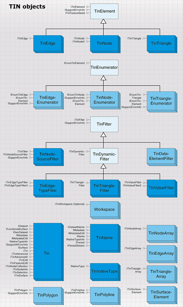
The Tin coclass is used for surface modeling and other forms of spatial analysis. A TIN is comprised of adjacent, non-overlapping, triangles. It is a complete planar graph that maintains topological relationships between its constituent elements: nodes, edges, and triangles. Point, polyline, and polygon features can be incorporated into a TIN. The vertices are used as nodes that are connected by edges to form triangles. Edges connect nodes that are close to one another. The partitioning of continuous space into triangular facets facilitates surface modeling because a very close approximation of a surface can be made by fitting triangles to planar, or near planar, patches on the surface. Input vector data is incorporated directly in the model and any resulting query or analysis will honor it exactly. Since the triangulation is based on proximity, interpolation neighborhoods are always comprised of the closest input data or samples. Proximity-based connectivity is useful for other analysis as well. For example, Thiessen polygons, also known as Voronoi diagrams, are constructed from TINs.
Certain licensing issues apply when working with TINs. Creation, editing, and analysis functions require a 3D Analyst license, while simple data management, such as copy, delete, and rename, only requires a core license. Additionally, the use of TIN layers for simple display and query only requires a core license.
TINs can be in-memory only objects or persisted to disk as datasets. A TIN can be made from scratch in memory, have data added, analysis performed, and be discarded without ever being written to disk. This is particularly useful when using a TIN as a temporary data structure to handle some analysis because the expense of writing to disk can be avoided. On the other hand, TINs are often created and saved to disk for use at a later time. The most common example of this is the use of a TIN as a surface model that will be used repeatedly over time.
The following code example is used to open an existing TIN using the ITinWorkspace interface:
[C#] // Create a TIN workspace factory.
Type factoryType=Type.GetTypeFromProgID("esriDataSourcesFile.TinWorkspaceFactory");
IWorkspaceFactory workspaceFactory=(IWorkspaceFactory)Activator.CreateInstance
(factoryType);
// Open a directory containing TINs as a workspace.
IWorkspace workspace=workspaceFactory.OpenFromFile(@"C:\Data\Tin", 0);
ITinWorkspace tinWorkspace=(ITinWorkspace)workspace;
// Open a TIN from the workspace.
ITin tin=tinWorkspace.OpenTin("Shelbyville");
' Create a TIN workspace factory.
Dim factoryType As Type=Type.GetTypeFromProgID("esriDataSourcesFile.TinWorkspaceFactory")
Dim workspaceFactory As IWorkspaceFactory=CType(Activator.CreateInstance(factoryType), IWorkspaceFactory)

' Open a directory containing TINs as a workspace.
Dim workspace As IWorkspace=workspaceFactory.OpenFromFile("C:\Data\Tin", 0)
Dim tinWorkspace As ITinWorkspace=CType(workspace, ITinWorkspace)

' Open a TIN from the workspace.
Dim tin As ITin=tinWorkspace.OpenTin("Shelbyville")
Several notable interfaces implemented by the Tin object are ITinAdvanced2, ITinEdit, and ISurface. ITinAdvanced2 provides access to basic properties and is a starting point for getting at the underlying data structure. ITinEdit is used for TIN construction and editing. ISurface provides surface analysis functions such as contouring, profiling, and volumetrics.
Triangles, edges, and nodes are the basic elements that comprise a TIN. For advanced TIN editing and analysis, you'll need access to these elements and the relationships between them. The TIN subsystem includes TinTriangle, TinEdge, and TinNode objects for this purpose as well as helper objects such as TinElementEnumerators and TinFilters that support iterative processing. The filters control which elements are passed through the enumerators. There's an enumerator for each TIN element type: TinNodeEnumerator, TinEdgeEnumerator, and TinTriangleEnumerator. A variety of filters can be used with the enumerators.
The available TIN filters are as follows:
The existing filters provide quite a bit of capability. Additionally, it's relatively easy to program custom filters to accommodate the specialized requirements of any application.
The TinPolyline and TinPolygon helper objects are used to access logical polyline and polygon features in a TIN for the sake of conversion or analysis. TinPolyline or TinPolygon is discovered dynamically by starting with a seed element (that is, edge or triangle) and interactively flooding outward to all coincident elements that share a given property of interest. For example, you can extract polygons representing areas of like slope given a seed triangle for each area and a filter that defines the slope range. These helper objects enable you to construct and access complex entities in a TIN based on any user defined criteria.
Data transfer
The data transfer subsystem contains objects for copying and converting data into and out of geodatabases.
Data conversion
The data conversion objects are detailed in the following diagram:

The two central data converter objects are FeatureDataConverter and GeoDBDataTransfer.
FeatureDataConverter will be familiar to users of ArcCatalog; the import facilities make extensive use of this coclass. GeoDBDataTransfer will also be familiar to users of ArcCatalog; the copy/paste functionality to copy datasets between geodatabases makes use of this class.
Some other objects and interfaces are useful in support of FeatureDataConverter and GeoDBDataTransfer and perform the following functions:
- Check for potential problems in your field names with IFieldChecker.
- Inspect data that is rejected during the conversion process with IEnumInvalidObject.
- Keep the end user informed with IFeatureProgress.
In addition, the IFeatureDataConverter interface provides methods to convert data between different formats.
The following code example shows conversion of a feature class to a new feature class in a given workspace:
[C#] public void ConvertFeatureClass(IFeatureClass sourceClass, IWorkspace
targetWorkspace)
{
// Create name objects for the source dataset and its workspace.
IDataset sourceDataset=(IDataset)sourceClass;
IFeatureClassName sourceFeatureClassName=(IFeatureClassName)
sourceDataset.FullName;
IWorkspace sourceWorkspace=sourceDataset.Workspace;
// Create a name object for the target workspace.
IDataset targetWorkspaceDataset=(IDataset)targetWorkspace;
IWorkspaceName targetWorkspaceName=(IWorkspaceName)
targetWorkspaceDataset.FullName;
// Create a name object for the target dataset.
IFeatureClassName targetFeatureClassName=new FeatureClassNameClass
{
Name="NewFeatClass1", WorkspaceName=targetWorkspaceName
};
// Use the field checker to perform field validation.
IFieldChecker fieldChecker=new FieldCheckerClass
{
InputWorkspace=sourceWorkspace, ValidateWorkspace=targetWorkspace
};
IFields targetFields=null;
IEnumFieldError enumFieldError=null;
fieldChecker.Validate(sourceClass.Fields, out enumFieldError, out targetFields);
// Convert the data.
IFeatureDataConverter featureDataConverter=new FeatureDataConverterClass();
featureDataConverter.ConvertFeatureClass(sourceFeatureClassName, null, null,
targetFeatureClassName, null, targetFields, null, 1000, 0);
}
Public Shared Sub ConvertFeatureClass(ByVal sourceClass As IFeatureClass, ByVal targetWorkspace As IWorkspace)
' Create name objects for the source dataset and its workspace.
Dim sourceDataset As IDataset=CType(sourceClass, IDataset)
Dim sourceFeatureClassName As IFeatureClassName=CType(sourceDataset.FullName, IFeatureClassName)
Dim sourceWorkspace As IWorkspace=sourceDataset.Workspace

' Create a name object for the target workspace.
Dim targetWorkspaceDataset As IDataset=CType(targetWorkspace, IDataset)
Dim targetWorkspaceName As IWorkspaceName=CType(targetWorkspaceDataset.FullName, IWorkspaceName)

' Create a name object for the target dataset.
Dim targetFeatureClassName As IFeatureClassName=New FeatureClassNameClass With _
                                                  { _
                                                  .Name="NewFeatClass1", _
                                                  .WorkspaceName=targetWorkspaceName _
                                                  }

' Use the field checker to perform field validation.
Dim fieldChecker As IFieldChecker=New FieldCheckerClass With _
                                    { _
                                    .InputWorkspace=sourceWorkspace, _
                                    .ValidateWorkspace=targetWorkspace _
                                    }
Dim targetFields As IFields=Nothing
Dim enumFieldError As IEnumFieldError=Nothing
fieldChecker.Validate(sourceClass.Fields, enumFieldError, targetFields)

' Convert the data.
Dim featureDataConverter As IFeatureDataConverter=New FeatureDataConverterClass()
featureDataConverter.ConvertFeatureClass(sourceFeatureClassName, Nothing, Nothing, targetFeatureClassName, Nothing, targetFields, Nothing, 1000, 0)
End Sub
The ConvertFeatureDataset method can import whole feature datasets. When using ConvertFeatureDataset and ConvertFeatureClass, if you specify Nothing for the OutputGeometryDef parameter, the spatial reference will be taken from the input data or the destination feature dataset and default spatial index data will be created. The InputQueryFilter parameter allows you to just import a subset of the input data.
EnumInvalidObject is a standard enumerator like many others in ArcObjects. It represents a set of objects that failed a data conversion process. The IEnumInvalidObject interface lets you step through the objects that failed conversion and gain access to InvalidObjectInfo. InvalidObjectInfo tells you why a particular row or feature could not be loaded. The IInvalidObjectInfo interface returns information about an object that could not be loaded. An example of the ErrorDescription property is: The coordinates or measures are out of bounds. The InvalidObjectID property will be -1 unless the source data is in a geodatabase.
A FieldChecker object is used to validate a fields collection. It is most often used in conjunction with FeatureDataConverter. FieldChecker is particularly useful when you are creating a new feature class based on an existing feature class, and the input and output data are in different formats. For example, a shapefile field name of UID would be invalid in an Oracle geodatabase since it is a reserved word in that database.
In addition to reporting the problems it finds, FieldChecker generates a new fields collection with standard fixes for the field name problems. In the previous example, a new field name of UID_ would be generated. The types of errors that the field checker detects are listed by esriFieldNameErrorType. When converting to a geodatabase, the field checker will also rename geometry fields to Shape and object ID fields to OBJECTID. No field errors are returned in this situation.
The IFieldChecker interface validates field names and table names relative to a particular workspace. If you do not set the ValidateWorkspace and InputWorkspace properties before validating the fields, FieldChecker assumes a default set of reserved words and invalid characters. This may cause you to rename fields unnecessarily if the problem does not apply to the data format to which you are converting. The ValidateTableName method will check a proposed table name against reserved words and invalid characters. It will not check to see if that table name is already being used in the workspace.
EnumFieldError is a standard enumerator like many others in ArcObjects. It represents a set of field names that would cause problems in a data conversion process. The IEnumFieldError interface lets you step through the field errors found by the field checker. Each element returned is a FieldError object. A FieldError object provides information about a problem with a field. The IFieldError interface tells you what kind of error was found and to what field it applies.
Distributed geodatabase
The distributed geodatabase objects are for working with checkout information for active checkouts in a geodatabase. They consist of the Replica, ReplicaDataset, and ReplicaDescription objects, which act as specifications for a geodatabase checkout. The ReplicaDescription object is also used for defining data to checkout or extract. The distributed geodatabase objects are detailed in the following diagram:

For further information see:
GeoDatabaseDistributed library overviewVersioning
Versioning allows multiple users to edit spatial and tabular data simultaneously in a long transaction environment. Users can directly modify the database without extracting data or locking features in advance. The object model provides functionality to create and administer versions, register and unregister classes as versioned, detect differences between versions, and reconcile and post versions. The versioning objects are detailed in the following diagram:
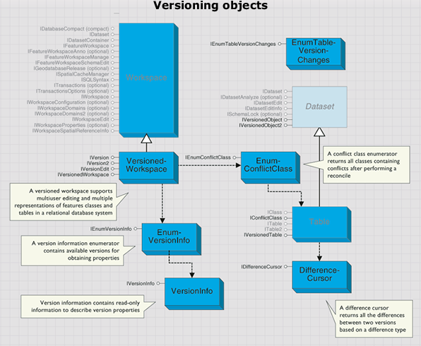
A VersionedWorkspace object is a workspace that supports multiuser editing and multiple representations of features classes and tables in a relational database system. VersionedWorkspaces support the IVersionedWorkspace interface. The VersionedWorkspace object is shown in the following diagram:
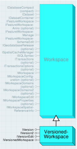
A list of all versions to which the user has permissions can be retrieved using the Versions property. The versions returned are either owned by the connected user or have public access. Versions returns an enumeration of all public versions and those owned by the connected user.
The DefaultVersion property can be used to retrieve the default version of the database. There is always a default version owned by the ArcSDE user.
The FindVersion method can be used to retrieve other versions by name. Version names are case sensitive and limited to 32 characters. Versioned workspace compression is available using the Compress method. Compressing a VersionedWorkspace will remove those database states not referenced by a version. Only the ArcSDE administrator user can execute the Compress method. FindVersion finds a specific version provided its name.
The IVersion interface is used to manage the properties of a version as well as create new versions. Creating a new version requires an existing version to be the parent of the new version. When the new version is created, the parent and child versions are identical.
The following code example can be used to update the Access property of the version:
[C#] IVersion version=(IVersion)workspace;
IVersionInfo versionInfo=version.VersionInfo;
if (versionInfo.IsOwner())
{
version.Access=esriVersionAccess.esriVersionAccessPublic;
}
Dim Version As IVersion=CType(workspace, IVersion)
Dim versionInfo As IVersionInfo=Version.VersionInfo
If versionInfo.IsOwner() Then
    Version.Access=esriVersionAccess.esriVersionAccessPublic
End If
The IVersionEdit interface is used to reconcile a version with a target version. Once reconciled, the object provides you the ability to work with representations of the version prior to editing, the prereconcile version, the reconcile version, and the common ancestor version. The common ancestor version represents the state of the database when the start editing version was originally created from the reconcile version (at the time when each version was identical).
You can only post a version that has first been reconciled with one of its ancestor versions. You are not limited to reconciling a version with its immediate parent version. Once you have performed the reconcile, the CanPost method will return true; however, if you perform an Undo operation, CanPost will become false.
CommonAncestorVersion returns the common ancestor version of this version and the reconcile version. ConflictClasses returns an enumeration of all classes containing conflicts. ModifiedClasses returns an enumeration of all the classes modified in the version.
PreReconcileVersion returns the version prior to reconciliation. ReconcileVersion returns the version against which this version is currently reconciling. StartEditingVersion returns the version before any edits were made. CanPost returns a Boolean if the version can be posted to the reconcile version.
Post applies the changes in the current version to the reconciled version. Reconcile merges the current edit version with a target version.
The following code example shows how an application can reconcile the current version with the default version. If conflicts are detected, you will have to interactively perform conflict resolution. If not, the application can verify that it can perform the post operation, then it can perform the post.
[C#] // Use IVersionEdit4 to reconcile.
IVersionEdit4 versionEdit4=(IVersionEdit4)workspace;
Boolean conflictsFound=versionEdit4.Reconcile4("SDE.DEFAULT", true, false, false,
true);
// Post.
if (versionEdit4.CanPost())
{
versionEdit4.Post("SDE.DEFAULT");
}
' Use IVersionEdit4 to reconcile.
Dim versionEdit4 As IVersionEdit4=CType(workspace, IVersionEdit4)
Dim conflictsFound As Boolean=versionEdit4.Reconcile4("SDE.DEFAULT", True, False, False, True)

' Post.
If versionEdit4.CanPost() Then
    versionEdit4.Post("SDE.DEFAULT")
End If
Reconcile4 reconciles the current edit version with the specified target version. The target version must be an ancestor of the current version or an error will be returned. The target version name passed in is case sensitive and should take the form {owner}.{version_name}—for example, SDE.DEFAULT. The first Boolean argument specifies whether locks should be obtained; true acquires the lock, while false does not. This should only be set to false if there is no intention of posting changes to default. The second Boolean argument specifies if the reconcile process should abort the reconcile if conflicts are detected for any class. Ideally, the second Boolean is only set to true when performing a reconcile in a batch type environment where you do not have the ability to interactively resolve conflicts. The third Boolean argument specifies if the conflicts will be resolved in favor of the child version. In this case, setting the Boolean argument to true will take the child representation over the conflicting changes to the parent. The forth and final Boolean argument columnLevel can be used to set the degree of conflict filtering present during a reconcile between versions. Setting this argument to true will only recognize conflicts at the attribute and not the row level. For instance, if geometry was updated on the target version and a different field was updated on the child, if this argument was set to true, no conflicts would be detected.
A conflict class enumerator returns all classes containing conflicts after performing a reconcile. Objects of this type are created through the IVersionEdit.ConflictClasses property. The enumeration contains a set of IConflictClass objects that specify the conflict classes that were found during the execution of IVersionEdit.Reconcile.
The IVersionInfo interface is a read-only collection of methods used to obtain the different properties of a version. To set the properties of a version, use the IVersion interface.
The DifferenceCursor object returns a cursor of object IDs and IRows based on the difference type used with IVersionedTable. The set of object IDs returned is dependent on the difference type category. For example, if the difference type DeleteNoChange is applied, the cursor will be empty for the table that has deleted the rows. In this case, the application will have to change the table the version references in the IVersionedTable interface.
The IVersionedObject and IVersionedObject2 interfaces are used to register and unregister feature datasets and classes as versioned. They will also return the current version that a dataset or table references.
Using the RegisterAsVersioned method on a feature dataset will register all classes in the dataset as versioned or, alternatively, you can use RegisterAsVersioned on an individual feature class. Only the feature dataset or feature class owner can register an object as versioned. The process will create two additional tables in the database. The IsRegisterAsVersioned property returns a Boolean if the dataset or class is registered in the database as versioned. When called on a feature dataset, if any class is not registered as versioned, false will be returned. The Version property returns the current version the object references. This ensures that the application is working with the correct version of the database. RegisterAsVersioned provides the ability to register and unregister a feature dataset as versioned. A true value will register the dataset or class as versioned, and a false value will unregister the dataset or class as versioned.
HasUncompressedEdits returns whether or not there are edits that have not yet been compressed.
The IVersionedObject3 interface is used to register and unregister classes as versioned with the option of moving edits to base. Using the RegisterAsVersioned3 method on a feature dataset will register all classes in the dataset as versioned or, alternatively, you can use RegisterAsVersioned3 to register an individual feature class. Only the feature dataset or feature class owner can register an object as versioned. The process creates two additional tables in the database.
The MovingEditsToBase argument can be used to specify if the class should be registered with the option of moving edits to base. If this property is set to false, the class will be registered but will not move edits to base. This is synonymous with calling IVersionedObject.RegisterAsVersioned(true).
A table in a versioned workspace implements two additional interfaces, IConflictClass and IVersionedTable. IConflictClass is obtained from the IEnumConflictClass enumeration. It is provided as a mechanism to work with the conflicting rows from each conflict class after performing a reconcile. If IVersionEdit.Reconcile has not been called prior to this, the classes will not be available.
The DeleteUpdates property returns an ISelectionSet of all the object IDs of rows that have been deleted in the edit version and updated in the target reconcile version. If no conflicts were detected, the selection set is null. HasConflicts returns a Boolean if the reconcile detects conflicts.
The UpdateDeletes property returns an ISelectionSet of all the object IDs of rows that have been updated in the edit version and deleted in the target reconcile version. If no conflicts were detected, the selection set is null.
The UpdateUpdates property returns an ISelectionSet of all the object IDs of rows that have been updated in the edit version and updated in the target reconcile version. If no conflicts were detected, the selection set is null.
The IVersionedTable interface can be used to detect the different conflict categories without first performing IVersionEdit.Reconcile. By specifying the appropriate esriDifferenceType, such as TypeDeleteUpdate or TypeInsert, IDifferenceCursor is returned with a set of OIDs and IRows for differences.
Differences returns a cursor that can be used to retrieve the rows by the difference type.
Archiving
Working with historical data allows you to access information about previous versions of the data. Archiving provides you the ability to store all temporal representations of a dataset, writing any changes made to an object to an associated archive table. This object model provides functionality to create historical versions that reference a specific moment in time. Since this version represents a specific moment in time, any queries against it will represent the view of the dataset at that particular moment. The archive objects are detailed in the following diagram:
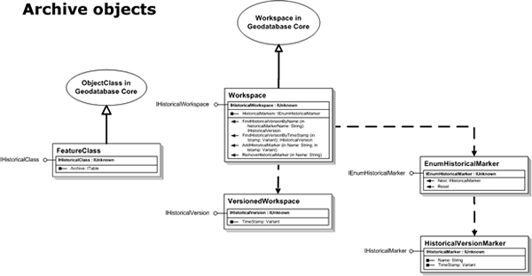 For a class to participate in archiving, it must be archiving enabled. This can be achieved through the IArchivableObject interface. Before enabling archiving on a class, it is good programming practice to check if the archive is already archiving through the IsArchiving property. The EnableArchiving method will enable archiving on a versioned object.
The IArchiveRegistrationInfo interface can be used to create a set of archive table names to be used in the enabling process. Conversely, the DisableArchiving method can be used to disable archiving on a class. The deleteArchive argument is used to specify whether the archive tables should be preserved as temporal tables in the database.
As mentioned in the previous paragraph, if a class is archiving enabled, it is considered an IArchivableClass. By registering an object for archiving, an archive table is created and an association between the table and the object class is made. It is for this reason that IArchivableClass is an optional interface supported by an ObjectClass. This interface has the Archive property that returns a pointer to the archive table associated with the archive class.
An optional interface supported by a workspace is the IHistoricalWorkspace interface. This interface provides functionality to add and remove historical markers that are named moments in time. An enumeration of historical markers present on the workspace can also be instantiated through the HistoricalMarkers property on this interface. The FindHistoricalVersionByName and FindHistoricalVersionByTimeStamp methods should be used to retrieve other historical versions that are present on the workspace.
The IHistoricalVersion interface is used to manage the properties of a historical version. This interface has one property, TimeStamp, which corresponds to the particular moment in time the historical version references.
A named historical version is essentially a HistoricalVersionMarker object. It can be created using the AddHistoricalMarker method and exists on the workspace similar to a transactional version. The IHistoricalMarker interface, which is supported by HistoricalVersionMarker, provides access to the properties of historical markers through the Name and TimeStamp properties.
The following code example demonstrates how to loop through the historical markers present on a workspace:
[C#] // Use IHistoricalWorkspace to get an enumerator of historical markers.
IHistoricalWorkspace historicalWorkspace=(IHistoricalWorkspace)workspace;
IEnumHistoricalMarker enumHistoricalMarker=historicalWorkspace.HistoricalMarkers;
enumHistoricalMarker.Reset();
// Iterate through the historical markers, displaying the properties of each.
IHistoricalMarker historicalMarker=null;
while ((historicalMarker=enumHistoricalMarker.Next()) != null)
{
Console.WriteLine("Name: '{0}', Time: '{1}'", historicalMarker.Name,
historicalMarker.TimeStamp);
}
' Use IHistoricalWorkspace to get an enumerator of historical markers.
Dim historicalWorkspace As IHistoricalWorkspace=CType(workspace, IHistoricalWorkspace)
Dim enumHistoricalMarker As IEnumHistoricalMarker=historicalWorkspace.HistoricalMarkers
enumHistoricalMarker.Reset()

' Iterate through the historical markers, displaying the properties of each.
Dim historicalMarker As IHistoricalMarker=enumHistoricalMarker.Next()
While Not historicalMarker Is Nothing
    Console.WriteLine("Name: '{0}', Time: '{1}'", historicalMarker.Name, historicalMarker.TimeStamp)
    historicalMarker=enumHistoricalMarker.Next()
End While
Name objects
A name object is a persistable object that identifies and locates a geodatabase object, such as a dataset or a workspace, or a map object such as a layer.
A name object supports an open method that allows the client to get an instance of the actual object (for example, the dataset or workspace) given the name object. Thus, a name object acts as a moniker that supports binding to the named object. The geodatabase name objects are detailed in the following diagram:
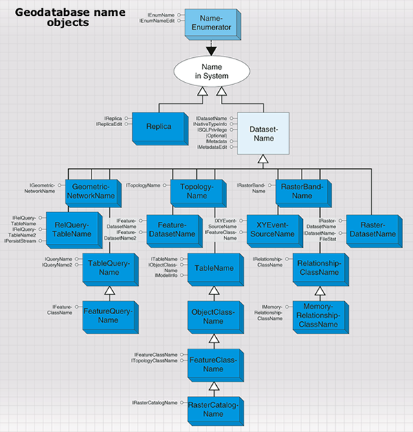
The geodatabase supports methods on workspaces that hand out name objects that can be used by browsing clients to display the names of datasets in the workspace and to instantiate any specific dataset. Name objects can also carry properties that describe the object being named. A browsing client can use these properties to display additional information about the object being named. A name object can also support methods to access metadata, or methods to change permissions on the actual object. In these cases, a name object can be used as a lightweight surrogate of the actual object until such time as further properties of the object are needed or additional methods on the object need to be called.
Name objects have public constructors and can be used to specify datasets that are yet to be created, for example, the output dataset to be created by a geoprocessing operation. There are several kinds of name objects—for example, workspace, table, feature class, feature dataset, raster, and relationship class.
A workspace name is a key component of any dataset name for datasets in the workspace. The IWorkspaceName interface lets you access the properties of a workspace name. The WorkspaceName object is shown in the following diagram:
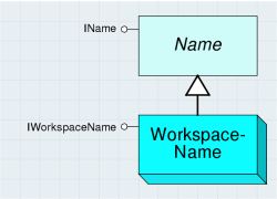
To create a new workspace name, you must set the WorkspaceFactoryProgID property followed by either PathName or ConnectionProperties.
The following code example creates a name object for a file geodatabase:
[C#] IWorkspaceName workspaceName=new WorkspaceNameClass
{
WorkspaceFactoryProgID="esriDataSourcesGDB.FileGDBWorkspaceFactory", PathName
=@"C:\Data\Usa.gdb"
};
Dim workspaceName As IWorkspaceName=New WorkspaceNameClass With _
{ _
.WorkspaceFactoryProgID="esriDataSourcesGDB.FileGDBWorkspaceFactory", _
.PathName="C:\Data\Usa.gdb" _
}
The workspace factories for all the workspaces are in the various DataSources libraries. At the end of the previous code example, the name object could be referring to an existing workspace or one that is to be created. If the workspace already exists, it can be opened with IName.Open—effectively, this procedure is equivalent to opening a workspace using Open or OpenFromFile on IWorkspaceFactory. If the workspace does not exist and is to be created, use IWorkspaceFactory.Create.
In some circumstances, you may already have a full workspace object but require a workspace name instead. The following code example shows you how to do this:
[C#] IDataset dataset=(IDataset)workspace;
IWorkspaceName workspaceName=(IWorkspaceName)dataset.FullName;
Dim dataset As IDataset=CType(workspace, IDataset)
Dim workspaceName As IWorkspaceName=CType(dataset.FullName, IWorkspaceName)
The Type, Category, WorkspaceFactoryProgID, and BrowseName properties all return information on the workspace.
DatasetName is an abstract class that covers name objects for datasets in a workspace. DatasetName objects identify and locate datasets within a workspace. In addition, they can carry additional properties that describe the named dataset. The DatasetName object is shown in the following diagram:
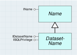
DatasetName objects support methods to access metadata for the named object (via the optional IMetadata interface) and to manage privileges for the dataset (via the ISQLPrivilege interface). The DatasetName object for an existing dataset can be obtained by reading the IDataset.FullName property. DatasetName objects can also be created to specify new datasets that are to be created by some operation.
The IDatasetName interface provides access to the basic properties of a dataset name object.
The Name property returns the identifier for the dataset within the context of its workspace. The value of the name property of the dataset name object (IDatasetName.Name) is the same as the value of the name property for the dataset (IDataset.Name).
The WorkspaceName property returns the workspace name object for the workspace containing the dataset being specified by this dataset name object.
You can use the IDataset.FullName property to get a dataset name object from the actual dataset object.
The following code example creates a feature class name object from a feature class:
[C#] IDataset dataset=(IDataset)featureClass;
IFeatureClassName featureClassName=(IFeatureClassName)dataset.FullName;
Dim dataset As IDataset=CType(featureClass, IDataset)
Dim featureClassName As IFeatureClassName=CType(dataset.FullName, IFeatureClassName)
A dataset name can also refer to a dataset that does not yet exist. This is useful when creating data, for example, with feature data converters.
The following code example makes a new feature class name—the key properties to set are Name and WorkspaceName:
[C#] // Create a workspace name object.
IWorkspaceName workspaceName=new WorkspaceNameClass
{
    WorkspaceFactoryProgID="esriDataSourcesGDB.FileGDBWorkspaceFactory", PathName
       =@"C:\Data\Usa.gdb"
};
// Create a feature class name object.
IDatasetName datasetName=new FeatureClassNameClass();
datasetName.WorkspaceName=workspaceName;
datasetName.Name="Land_Use";
' Create a workspace name object.
Dim workspaceName As IWorkspaceName=New WorkspaceNameClass With _
                                      { _
                                      .WorkspaceFactoryProgID="esriDataSourcesGDB.FileGDBWorkspaceFactory", _
                                      .PathName="C:\Data\Usa.gdb" _
                                      }
' Create a feature class name object.
Dim datasetName As IDatasetName=New FeatureClassNameClass()
datasetName.WorkspaceName=workspaceName
datasetName.Name="Land_Use"
The ISQLPrivilege optional interface provides information about the permissions you have on a database object; it also provides information about how to change the permissions for other users. It only applies to those datasets that are stored within a multiuser SQL environment, most typically an ArcSDE geodatabase. ISQLPrivilege controls access to database objects.
The esriSQLPrivilege enumeration defines values that can be used with ISQLPrivilege.
The bitwise OR operation can be applied to the values if more than one privilege applies (this is equal to summing the integer values). For example, if the SQLPrivileges property returns a value of 9, you have select and delete permission on the dataset but not insert or update. A value of 15 indicates full privileges.
The following code example grants select and update privileges to a user called Scott. The dataset name could be a feature dataset, in which case Scott would receive the privileges on all the contents of the feature dataset.
[C#] // Use a bitwise OR to create a combination of privileges.
int privileges=(int)esriSQLPrivilege.esriSelectPrivilege | (int)
esriSQLPrivilege.esriUpdatePrivilege;
// Use ISQLPrivilege to grant the privileges.
ISQLPrivilege sqlPrivilege=(ISQLPrivilege)datasetName;
sqlPrivilege.Grant("Scott", privileges, true);
' Use a bitwise OR to create a combination of privileges.
Dim privileges As Integer=CInt(esriSQLPrivilege.esriSelectPrivilege) Or CInt(esriSQLPrivilege.esriUpdatePrivilege)

' Use ISQLPrivilege to grant the privileges.
Dim sqlPrivilege As ISQLPrivilege=CType(datasetName, ISQLPrivilege)
sqlPrivilege.Grant("Scott", privileges, True)
The following are types of DatasetName objects in the geodatabase:
- RelQueryTableName
- TableQueryName
- FeatureQueryName
- FeatureDatasetName
- RelationshipClassName
- MemoryRelationshipClassName
- TableName
- ObjectClassName
- FeatureClassName
- GeometricNetworkName
- TopologyName
- XYEventSourceName
- RasterCatalogName
- RasterDatasetName
- RasterBandName
Relationship query table
The relationship query table subsystem contains objects for working with on-the-fly table joins (RelQueryTable) and memory relationships (MemoryRelationshipClass). The on-the-fly table join objects are detailed in the following diagram:
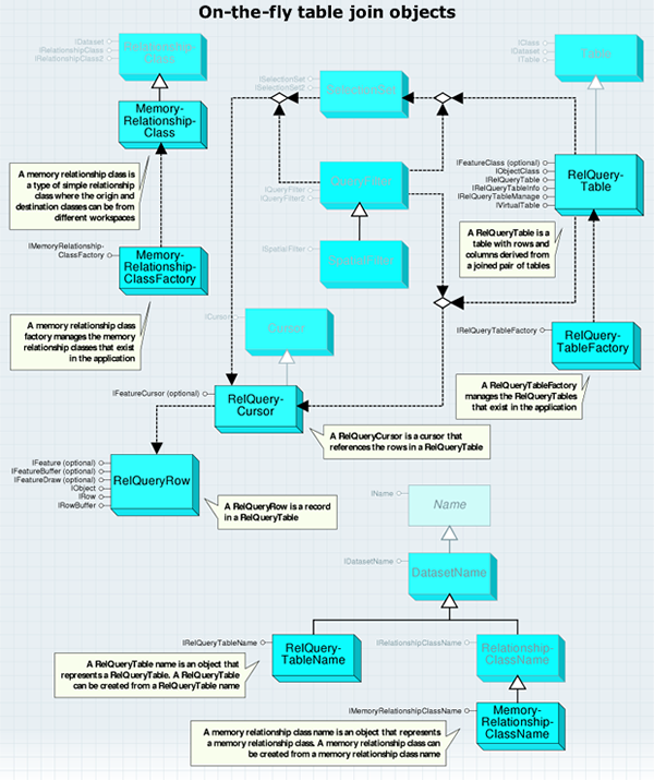
The MemoryRelationshipClassFactory class is used to create memory relationship classes. You must use either a MemoryRelationshipClassFactory or a MemoryRelationshipClassName object to create new memory relationship classes.
As with workspace factories, MemoryRelationshipClassFactory is a singleton object. This means that you can have only one instance of this object in a process.
The IMemoryRelationshipClassFactory interface provides an Open method that creates a MemoryRelationshipClass object. MemoryRelationshipClass is a simple (non composite), nonattributed relationship class that does not support relationship rules. The MemoryRelationshipClass object is shown in the following diagram:
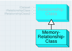
MemoryRelationshipClass inherits from RelationshipClass and, although it implements the same interfaces, not all properties and methods are supported. This section reviews each of these interfaces and describes which properties and methods behave differently or are not supported with memory relationship classes.
The IRelationshipClass interface provides information on how the relationship class was defined, functionality to create and delete individual relationships, and methods to find related objects.
The properties and methods of IRelationshipClass not listed in the following table behave the same way with memory relationship classes as they do with other relationship classes.
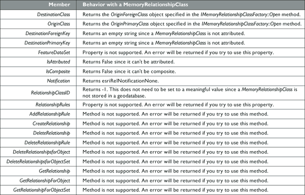
The following code example creates a MemoryRelationshipClass between the us_states feature class and the us_counties feature class. It then uses MemoryRelationshipClass to print the counties that appear in a known state.
[C#] // Open the origin and destination classes.
IFeatureWorkspace featureWorkspace=(IFeatureWorkspace)workspace;
IFeatureClass originClass=featureWorkspace.OpenFeatureClass("us_states");
IObjectClass destinationClass=(IObjectClass)featureWorkspace.OpenTable(
"us_counties");
// Create a memory relationship class factory and open a relationship class with it.
Type relClassFactoryType=Type.GetTypeFromProgID(
"esriGeodatabase.MemoryRelationshipClassFactory");
IMemoryRelationshipClassFactory memRelClassFactory=
(IMemoryRelationshipClassFactory)Activator.CreateInstance(relClassFactoryType);
IRelationshipClass memRelClass=memRelClassFactory.Open("StatesCounties",
originClass, "STATE_ID", destinationClass, "STATE_ID", "Contains", "Is in",
esriRelCardinality.esriRelCardinalityOneToMany);
// Find the counties related to the state with an ObjectID of 1.
IFeature originFeature=originClass.GetFeature(1);
ISet relatedSet=memRelClass.GetObjectsRelatedToObject(originFeature);
relatedSet.Reset();
// Iterate through the set while finding the names of the counties.
int nameIndex=destinationClass.FindField("NAME");
object setObject=null;
while ((setObject=relatedSet.Next()) != null)
{
IRow row=(IRow)setObject;
Console.WriteLine("OID: {0}, NAME: {1}", row.OID, row.get_Value(nameIndex));
}
' Open the origin and destination classes.
Dim featureWorkspace As IFeatureWorkspace=CType(workspace, IFeatureWorkspace)
Dim originClass As IFeatureClass=featureWorkspace.OpenFeatureClass("us_states")
Dim destinationClass As IObjectClass=CType(featureWorkspace.OpenTable("us_counties"), IObjectClass)

' Create a memory relationship class factory and open a relationship class with it.
Dim relClassFactoryType As Type=Type.GetTypeFromProgID("esriGeodatabase.MemoryRelationshipClassFactory")
Dim memRelClassFactory As IMemoryRelationshipClassFactory=CType(Activator.CreateInstance(relClassFactoryType), IMemoryRelationshipClassFactory)
Dim memRelClass As IRelationshipClass=memRelClassFactory.Open("StatesCounties", originClass, "STATE_ID", _
                                        destinationClass, "STATE_ID", "Contains", "Is in", esriRelCardinality.esriRelCardinalityOneToMany)

' Find the counties related to the state with an ObjectID of 1.
Dim originFeature As IFeature=originClass.GetFeature(1)
Dim relatedSet As ISet=memRelClass.GetObjectsRelatedToObject(originFeature)
relatedSet.Reset()

' Iterate through the set while finding the names of the counties.
Dim nameIndex As Integer=destinationClass.FindField("NAME")
Dim setObject As Object=relatedSet.Next()
While Not setObject Is Nothing
    Dim row As IRow=CType(setObject, IRow)
    Console.WriteLine("OID: {0}, NAME: {1}", row.OID, row.Value(nameIndex))
    setObject=relatedSet.Next()
End While
A RelQueryTableFactory object manages the RelQueryTables in the application. You must use either a RelQueryTableFactory or a RelQueryTableName object to create RelQueryTables.
As with the WorkspaceFactory objects, RelQueryTableFactory is a singleton object. This means that you can only have one instance of this object in a process.
The IRelQueryTableFactory interface provides an Open method to define the data RelQueryTable represents and how that data is accessed. The following table describes in more detail the meaning of each of the input parameters:
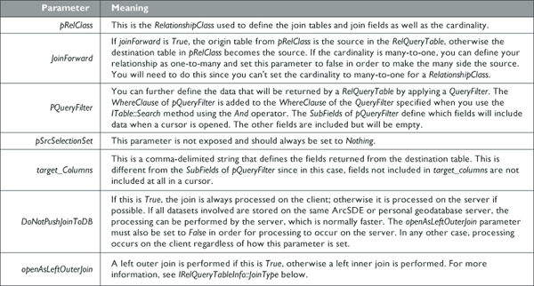
RelationshipClass is used when creating RelQueryTable to specify the tables involved and the fields on which the join is based. RelationshipClass can be stored in a geodatabase or created in memory. Memory relationship classes can include tables that belong to different data sources. Therefore, RelQueryTable can join tables from different data sources. The RelQueryTable object is shown in the following diagram:

RelQueryTable includes a source table or feature class and a destination table or feature class. If you step through a cursor opened from RelQueryTable, each row includes the columns from both input tables. The fields from the source appear on the left, while the fields from the destination appear on the right as shown in the following graphic. Each row from the table is composed of the primary and foreign keys from IRelationshipClass to produce a single row. Shapes can only be retrieved from the source table. If the destination table has a geometry field, it will not be included in RelQueryTable.

When you perform a join in ArcMap, a RelQueryTable object is created and used as the table or layer data source for all display purposes. In ArcMap, you can use the IDisplayTable.DisplayTable property to get a joined table or layer RelQueryTable.
Since a RelQueryTable implements IObjectClass and IFeatureClass and inherits from Table, it can be treated like any other Table or FeatureClass. The IFeatureClass interface is implemented only when the source is FeatureClass. A RelQueryTable cursor is read only, so you must edit the source and destination to change the data.
RelQueryTable is designed to work with relationships that have one-to-one or many-to-one cardinality. If the cardinality is one-to-many, a row from the source will be associated with the first matching row in the destination—any other matching rows are ignored. A RelationshipClass with a many-to-many cardinality is not supported and will cause an error. If the relationship has a cardinality of one-to-many or many-to-many, use RelationshipClass objects to access the data. If the cardinality is really one-to-one but the relationship is defined as one-to-many, RelQueryTable will still process correctly.
RelQueryTable will have an ObjectID if the source has an ObjectID. When initialized, RelQueryTable uses the values from the source’s ObjectID field to define its ObjectIDs. If the source lacks an ObjectID field, RelQueryTable can still access the data, but there will be limitations, such as an inability to select rows.
By definition, ObjectIDs must be unique. The reason relationships with one-to-many cardinality match one row from the source to only one row in the destination is to prevent repeating ObjectIDs in RelQueryTable. Repeating ObjectIDs will cause many objects, such as SelectionSets and table windows, to behave incorrectly.
The following code example creates a RelQueryTable from the memory relationship class created in the previous example (note that the second parameter of Open, "join forward", is false due to the one-to-many nature of the relationship class):
[C#] // Create a RelQueryTableFactory.
Type rqtFactoryType=Type.GetTypeFromProgID("esriGeodatabase.RelQueryTableFactory");
IRelQueryTableFactory rqtFactory=(IRelQueryTableFactory)Activator.CreateInstance
(rqtFactoryType);
// Open a RelQueryTable using a memory relationship class.
IRelQueryTable relQueryTable=rqtFactory.Open(memRelClass, false, null, null, null,
true, true);
// Display the number of rows in the RelQueryTable.
ITable table=(ITable)relQueryTable;
Console.WriteLine("RelQueryTable row count: {0}", table.RowCount(null));
' Create a RelQueryTableFactory.
Dim rqtFactoryType As Type=Type.GetTypeFromProgID("esriGeodatabase.RelQueryTableFactory")
Dim rqtFactory As IRelQueryTableFactory=CType(Activator.CreateInstance(rqtFactoryType), IRelQueryTableFactory)

' Open a RelQueryTable using a memory relationship class.
Dim relQueryTable As IRelQueryTable=rqtFactory.Open(memRelClass, False, Nothing, Nothing, Nothing, True, True)

' Display the number of rows in the RelQueryTable.
Dim table As ITable=CType(relQueryTable, ITable)
Console.WriteLine("RelQueryTable row count: {0}", table.RowCount(Nothing))
The IRelQueryTable interface allows you to get the source and destination as well as the RelationshipClass or MemoryRelationshipClass used to define the RelQueryTable. The source and destination can be tables, feature classes, or even other RelQueryTables.
For example, if you wanted to join two tables to a feature class, you would first create RelQueryTableA to join one of the tables to the feature class. You would then create RelQueryTableB to join the second table to RelQueryTableA. RelQueryTableA would be the source for RelQueryTableB. The following diagram illustrates how this works:
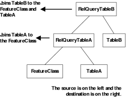
RelQueryCursor is created when you open a cursor on RelQueryTable. You can use methods such as Search from ITable and IFeatureClass to open the cursor. Since it inherits from Cursor, it implements ICursor and will implement IFeatureCursor if RelQueryTable has geometry. The RelQueryCursor object is shown in the following diagram:
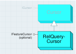
RelQueryCursor is read only; therefore, performing edits using the IRow.Delete and IRow.Store methods is not supported. Also, trying to open an insert or update cursor will result in an error since there is no insert or update RelQueryCursor. The ICursor interface provides access to a set of rows.
The following table outlines how the properties and methods of ICursor behave when used on RelQueryCursor:
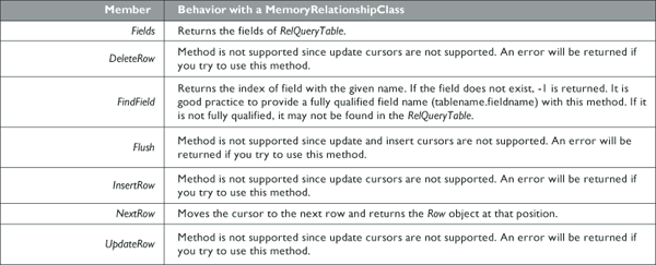
RelQueryRow can be obtained from RelQueryCursor (ICursor.NextRow) or methods such as ITable.GetRow. The ITable.CreateRow method is not supported and will return an error if used.
A MemoryRelationshipClassName object is a representation of a MemoryRelationshipClass object. MemoryRelationshipClassName can be used to create, work with existing, or persist MemoryRelationshipClasses. The MemoryRelationshipClassName object is shown in the following diagram:
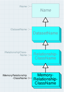
The IMemoryRelationshipClassName interface contains properties that correspond to the parameters used with the IMemoryRelationshipClassFactory.Open method. These include the Origin and Destination tables, the fields, and the forward and backward pathnames.
The only parameters from the IMemoryRelationshipClassFactory.Open method that don’t have a corresponding property in IMemoryRelationshipClassName are the name and the cardinality. The name can be set using the IDatasetName interface, and the cardinality can be set using the IRelationshipClassName interface. Both of these interfaces are inherited by MemoryRelationshipClassName.
When creating a new MemoryRelationshipClass using a MemoryRelationshipClassName object, only the properties previously described need to be set.
The following code example creates a new MemoryRelationshipClass from a MemoryRelationshipClassName instance:
[C#] // Create a new memory relationship class name object.
IMemoryRelationshipClassName memRelClassName=new MemoryRelationshipClassNameClass
{
Name="StatesCounties", OriginName=originName, DestinationName =
destinationName, OriginPrimaryKey="STATE_ID", OriginForeignKey=
"STATE_ID", ForwardPathLabel="Contains", BackwardPathLabel="Is in",
Cardinality=esriRelCardinality.esriRelCardinalityOneToMany
};
// Open the memory relationship class using IName.Open.
IName name=(IName)memRelClassName;
IRelationshipClass memRelClass=(IRelationshipClass)name.Open();
' Create a new memory relationship class name object.
Dim memRelClassName As IMemoryRelationshipClassName=New MemoryRelationshipClassNameClass With _
                                                      { _
                                                      .Name="StatesCounties", _
                                                      .OriginName=originName, _
                                                      .DestinationName=destinationName, _
                                                      .OriginPrimaryKey="PROPERTY_I", _
                                                      .OriginForeignKey="PROPERTY_ID", _
                                                      .ForwardPathLabel="Contains", _
                                                      .BackwardPathLabel="Is in", _
                                                      .Cardinality=esriRelCardinality.esriRelCardinalityOneToMany _
                                                      }

' Open the memory relationship class using IName.Open.
Dim Name As IName=CType(memRelClassName, IName)
Dim memRelClass As IRelationshipClass=CType(Name.Open(), IRelationshipClass)
RelQueryTableName is a representation of a RelQueryTable object. RelQueryTableName can be used to create, work with existing, or persist RelQueryTables. The RelQueryTableName object is shown in the following diagram:
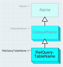
The IRelQueryTableName interface contains properties that correspond to the parameters used with the IRelQueryTableFactory.Open method previously described.
The following code example shows how to create RelQueryTable from a RelQueryTableName object. In this example, the MemoryRelationshipClassName has already been created.
[C#] // Create a new RelQueryTable name object.
IRelQueryTableName relQueryTableName=new RelQueryTableNameClass
{
RelationshipClassName=(IName)memRelClassName, ForwardDirection=false,
SrcQueryFilter=null, SrcSelectionSet=null, TargetColumns=null,
DoNotPushJoinToDB=true, LeftOuterJoin=true
};
// Open the RelQueryTable using IName.Open.
IName name=(IName)relQueryTableName;
IRelQueryTable relQueryTable=(IRelQueryTable)name.Open();
' Create a new RelQueryTable name object.
Dim relQueryTableName As IRelQueryTableName=New RelQueryTableNameClass With _
                                              { _
                                              .RelationshipClassName=CType(memRelClassName, IName), _
                                              .ForwardDirection=False, _
                                              .SrcQueryFilter=Nothing, _
                                              .SrcSelectionSet=Nothing, _
                                              .TargetColumns=Nothing, _
                                              .DoNotPushJoinToDB=True, _
                                              .LeftOuterJoin=True _
                                              }

' Open the RelQueryTable using IName.Open.
Dim Name As IName=CType(relQueryTableName, IName)
Dim relQueryTable As IRelQueryTable=CType(Name.Open(), IRelQueryTable)
The IDataset.FullName method can be used on an existing RelQueryTable object to get a corresponding RelQueryTableName object.
Raster
The raster subsystem contains objects for accessing and working with rasters, raster datasets, and raster catalogs. These objects are used for accessing both file-based raster data as well as raster data stored in a geodatabase. The raster objects are detailed in the following diagram:
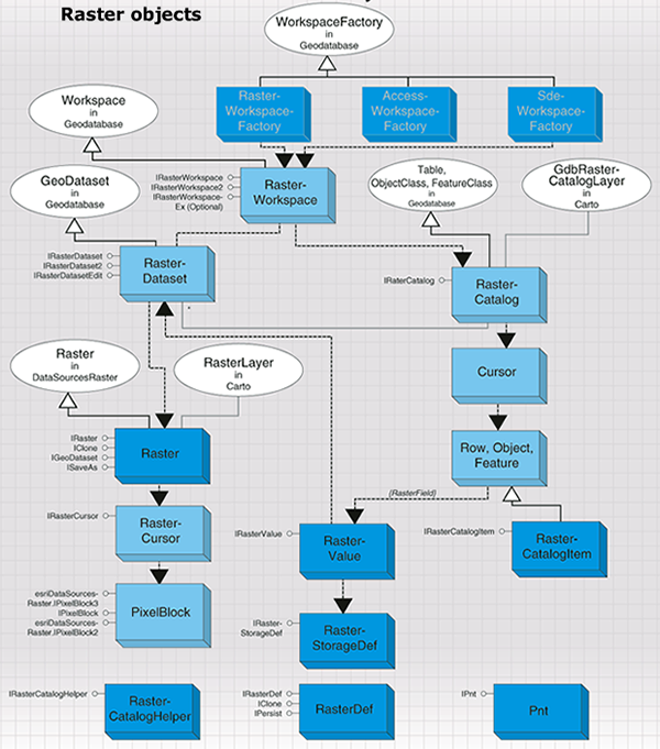
Raster data access objects
Raster data consists of a rectangular array of equally spaced cells, which taken as a whole represent thematic, spectral, or picture data. Raster data can represent everything from qualities of a land surface, such as elevation or vegetation, to satellite images, scanned maps, and photographs. The raster data access objects are detailed in the following diagram:
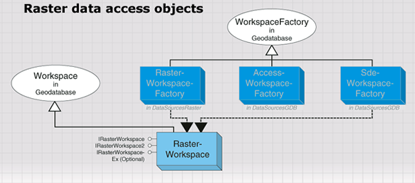
ArcGIS supports file-based raster data such as GRID, TIFF, ERDAS IMAGINE, JPEG, and so on. It also supports raster data in geodatabases, including personal geodatabases and ArcSDE geodatabases. Regardless of the various data sources, two data types are used to represent raster data: raster dataset and raster catalog. A raster dataset represents an existing dataset stored on disk in a particular raster format or in a geodatabase, while a raster catalog manages a collection of raster datasets as one entity—a special feature class in a geodatabase. A raster dataset consists of one or more raster bands. A raster dataset can contain pyramids, statistics, and colormaps that are used to provide fast access and better display. A raster dataset can also contain a raster table.
The RasterWorkspaceFactory class is used to initialize a raster workspace for file-based rasters, while rasters stored in geodatabases should be accessed by casting the geodatabase workspace to the IRasterWorkspaceEx interface.
The following code example opens a raster workspace for a given directory:
[C#] // Create a raster workspace factory and open a folder of rasters as a workspace.
Type factoryType=Type.GetTypeFromProgID(
"esriDataSourcesRaster.RasterWorkspaceFactory");
IWorkspaceFactory workspaceFactory=(IWorkspaceFactory)Activator.CreateInstance
(factoryType);
IWorkspace workspace=workspaceFactory.OpenFromFile(@"C:\Data\Rasters", 0);
IRasterWorkspace2 rasterWorkspace2=(IRasterWorkspace2)workspace;
' Create a raster workspace factory and open a folder of rasters as a workspace.
Dim factoryType As Type=Type.GetTypeFromProgID("esriDataSourcesRaster.RasterWorkspaceFactory")
Dim workspaceFactory As IWorkspaceFactory=CType(Activator.CreateInstance(factoryType), IWorkspaceFactory)
Dim workspace As IWorkspace=workspaceFactory.OpenFromFile("C:\Data\Rasters", 0)
Dim rasterWorkspace2 As IRasterWorkspace2=CType(workspace, IRasterWorkspace2)
The following code example opens a file geodatabase as a raster workspace:
[C#] // Create a file GDB workspace factory and open a geodatabase as a workspace.
Type factoryType=Type.GetTypeFromProgID(
"esriDataSourcesGDB.FileGDBWorkspaceFactory");
IWorkspaceFactory workspaceFactory=(IWorkspaceFactory)Activator.CreateInstance
(factoryType);
IWorkspace workspace=workspaceFactory.OpenFromFile(@"C:\Data\Public.gdb", 0);
IRasterWorkspaceEx rasterWorkspaceEx=(IRasterWorkspaceEx)workspace;
' Create a file GDB workspace factory and open a geodatabase as a workspace.
Dim factoryType As Type=Type.GetTypeFromProgID("esriDataSourcesGDB.FileGDBWorkspaceFactory")
Dim workspaceFactory As IWorkspaceFactory=CType(Activator.CreateInstance(factoryType), IWorkspaceFactory)
Dim workspace As IWorkspace=workspaceFactory.OpenFromFile("C:\Data\Public.gdb", 0)
Dim rasterWorkspaceEx As IRasterWorkspaceEx=CType(workspace, IRasterWorkspaceEx)
The three interfaces on a Workspace object provide access to RasterDataset and RasterCatalog objects. IRasterWorkspace and IRasterWorkspace2 are used to open and create a file-based RasterDataset.
The following code example opens an image file in a given directory:
[C#] // Open a raster dataset from a file-based raster workspace.
IRasterDataset rasterDataset=rasterWorkspace2.OpenRasterDataset("airphoto.img");
' Open a raster dataset from a file-based raster workspace.
Dim rasterDataset As IRasterDataset=rasterWorkspace2.OpenRasterDataset("airphoto.img")
To create a file-based raster dataset, the origin, width, and height of the raster dataset must be specified in addition to other required parameters, and a raster dataset with the specified dimension and default pixel values will be created. The default pixel values of the raster dataset can be modified by writing pixel blocks to the dataset. This process is shown in the following code example:
[C#] // Create a new raster dataset.
IRasterDataset rasterDataset=rasterWorkspace2.CreateRasterDataset("MyImage.img",
"IMAGINE Image", originPoint, 200, 100, 1, 1, 1, rstPixelType.PT_UCHAR,
spatialReference, true);
' Create a new raster dataset.
Dim rasterDataset As IRasterDataset=rasterWorkspace2.CreateRasterDataset("MyImage.img", "IMAGINE Image", originPoint, 200, 100, 1, 1, 1, rstPixelType.PT_UCHAR, spatialReference, True)
IRasterWorkspaceEx provides access to RasterDataset and RasterCatalog. IRasterWorkspaceEx, through an Access workspace, accesses a file-based RasterDataset and a RasterCatalog in a personal geodatabase. IRasterWorkspaceEx, through a database workspace, accesses a database RasterDataset and a RasterCatalog in an ArcSDE geodatabase.
The following code example opens a raster dataset and a raster catalog from a geodatabase:
[C#] // Open a raster dataset from a geodatabase.
IRasterDataset rasterDataset=rasterWorkspaceEx.OpenRasterDataset("airphoto");
// Open a raster catalog from a geodatabase.
IRasterCatalog rasterCatalog=rasterWorkspaceEx.OpenRasterCatalog("airphoto_cat");
' Open a raster dataset from a geodatabase.
Dim rasterDataset As IRasterDataset=rasterWorkspaceEx.OpenRasterDataset("airphoto")

' Open a raster catalog from a geodatabase.
Dim rasterCatalog As IRasterCatalog=rasterWorkspaceEx.OpenRasterCatalog("airphoto_cat")
Creating a raster dataset in a geodatabase creates an empty raster dataset with no dimension, which is basically a placeholder for some attribute of the raster dataset, such as the number of bands, pixel type, RASTER field properties, or GEOMETRY field properties. Once the empty raster dataset is created, raster pixels can be appended from other raster data by mosaicking.
The following code example creates a raster dataset in a geodatabase:
[C#] // Create a RasterStorageDef object.
IRasterStorageDef rasterStorageDef=new RasterStorageDefClass();
rasterStorageDef.CompressionType =
esriRasterCompressionType.esriRasterCompressionJPEG2000;
// Create a RasterDef object.
IRasterDef rasterDef=new RasterDefClass();
rasterDef.SpatialReference=spatialReference;
// Create the raster dataset.
IRasterDataset rasterDataset=rasterWorkspaceEx.CreateRasterDataset("Redlands", 1,
rstPixelType.PT_UCHAR, rasterStorageDef, null, rasterDef, null);
' Create a RasterStorageDef object.
Dim rasterStorageDef As IRasterStorageDef=New RasterStorageDefClass()
rasterStorageDef.CompressionType=esriRasterCompressionType.esriRasterCompressionJPEG2000

' Create a RasterDef object.
Dim rasterDef As IRasterDef=New RasterDefClass()
rasterDef.SpatialReference=spatialReference

' Create the raster dataset.
Dim rasterDataset As IRasterDataset=rasterWorkspaceEx.CreateRasterDataset("Redlands", 1, rstPixelType.PT_UCHAR, rasterStorageDef, Nothing, rasterDef, Nothing)
Raster datasets
The raster dataset objects are detailed in the following diagram:
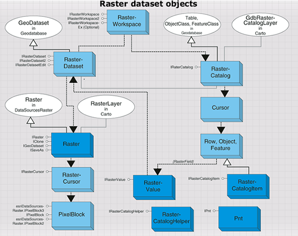
The RasterDataset object represents a raster dataset stored in a file system or in a geodatabase. RasterDataset is composed of one or more persistent raster bands. The RasterDataset object performs basic dataset management functions, such as copy, rename, and delete. It can also be used to examine dataset properties, such as raster format, extent, spatial reference, number of bands, and so on. The RasterDataset object is shown in the following diagram:
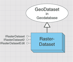
RasterDataset can be used to change some of the properties of the dataset. For example, RasterDataset can be used to change the spatial reference associated with the dataset, to manipulate the colormap of the raster dataset, to build pyramids (reduced-resolution datasets) that improve display performance for large raster datasets, and to build statistics that enhance raster rendering. The RasterDataset object can merge pixels from another raster dataset to itself.
The following code example, assuming that raster (IRaster) and rasterColorMap (IRasterColormap) have been created, alters the dataset's colormap and mosaic raster to the raster dataset:
[C#] // Alter the raster dataset's colormap and mosaic pixels from the raster to the dataset.
IRasterDatasetEdit rasterDatasetEdit=(IRasterDatasetEdit)rasterDataset;
rasterDatasetEdit.AlterColormap(rasterColormap);
rasterDatasetEdit.Mosaic(raster, 0.5);
' Alter the raster dataset's colormap and mosaic pixels from the raster to the dataset.
Dim rasterDatasetEdit As IRasterDatasetEdit=CType(rasterDataset, IRasterDatasetEdit)
rasterDatasetEdit.AlterColormap(rasterColormap)
rasterDatasetEdit.Mosaic(raster, 0.5)
RasterDataset can be saved to another format using ISaveAs.
The following code example saves a raster dataset to an IMAGINE format as well as to a geodatabase:
[C#] ISaveAs saveAs=(ISaveAs)rasterDataset;
saveAs.SaveAs("Redlands.img", rasterWorkspace, "IMAGINE Image");
saveAs.SaveAs("Redlands", workspace, "SDR");
Dim saveAs As ISaveAs=CType(rasterDataset, ISaveAs)
saveAs.SaveAs("Redlands.img", rasterWorkspace, "IMAGINE Image")
saveAs.SaveAs("Redlands", workspace, "SDR")
RasterDataset supports the IRasterBandCollection interface; however, adding or removing bands has no effect on RasterDataset. The IRasterBandCollection.SaveAs method plays the same role as ISaveAs.SaveAs.
The RasterDataset object can be used to initiate a Raster or a RasterBand object representing other aspect of the data.
The following code example returns the first raster band from a raster dataset:
[C#] IRasterBandCollection rasterBandCollection=(IRasterBandCollection)rasterDataset;
IRasterBand rasterBand=rasterBandCollection.Item(0);
Dim rasterBandCollection As IRasterBandCollection=CType(rasterDataset, IRasterBandCollection)
Dim rasterBands As IRasterBand=rasterBandCollection.Item(0)
Two methods can be used to create a Raster object from RasterDataset. The CreateFullRaster method creates a raster with all the properties from the raster dataset, such as number of bands and width and height of the raster dataset; while the CreateDefaultRaster method creates a raster that has a square cell size and contains only three raster bands if the dataset has more than three bands. The three bands are the default bands used in a raster RGB renderer and are determined by the settings for default raster behavior made on the RasterDefaultsEnv object in the Carto library.
The IRasterWorkspace interface and the IRasterWorkspaceEx interface, through an Access workspace, create a file-based RasterDataset; while the IRasterWorkspaceEx interface, through a database workspace, creates a database RasterDataset. A file-based RasterDataset and database RasterDataset work the same way except on a few interfaces. For example, the ITemporaryDataset and IWorldFileExport interfaces are not supported by a database RasterDataset and the IRasterPyramid2 interface is not supported by a file-based RasterDataset.
In addition to accessing through a workspace, RasterDataset can also be retrieved from a band in the dataset using the RasterDataset property. To access RasterDataset from a Raster object, first access a band from Raster, then obtain a reference to the dataset from the band. This technique is shown in the following code example:
[C#] IRasterBandCollection bandCollection=(IRasterBandCollection)raster;
IRasterBand rasterBand=bandCollection.Item(0);
IRasterDataset rasterDataset=rasterBand.RasterDataset;
Dim bandCollection As IRasterBandCollection=CType(raster, IRasterBandCollection)
Dim rasterBand As IRasterBand=bandCollection.Item(0)
Dim rasterDataset As IRasterDataset=rasterBand.RasterDataset
Raster bands
The RasterBand object represents an existing band of a raster dataset. This band can be the only band in a single-band raster dataset or one band in a multiband raster dataset. RasterBand can be accessed from either Raster or RasterDataset as previous code examples have demonstrated but, regardless of whether it is derived from the static RasterDataset or the transient Raster, RasterBand always represents a static band of raster data. A raster band accessed from a file-based RasterDataset is a file-based RasterBand, and a raster band accessed from a database RasterDataset is a database RasterBand. Some interfaces are only supported by a file-based RasterBand, not by a database RasterBand.
A raster band contains pixel values in the band. It can also contain statistics, a colormap, a histogram, or a table, which are all accessible through RasterBand.
The following code example accesses a raster colormap:
[C#] Boolean hasColormap=false;
rasterBand.HasColormap(out hasColormap);
if (hasColormap)
{
IRasterColormap rasterColormap=rasterBand.Colormap;
// Use the colormap...
}
Dim hasColormap As Boolean=False
rasterBand.HasColormap(hasColormap)
If hasColormap Then
    Dim rasterColormap As IRasterColormap=rasterBand.Colormap
    ' Use the colormap...
End If
RasterBand supports the IRawPixels interface, which allows you to read and write pixels directly to the band. For a file-based RasterBand, use the AcquireCache method before writing pixel blocks. This can prevent unnecessary pyramid building and enhance performance. A file-based RasterBand also supports the IRasterTransaction interface, which can be used to manage the transaction of editing pixels.
Raster object
The Raster object, in contrast to the static RasterDataset and RasterBand objects, is transient in nature and can be modified without affecting the source data. This allows the raster to represent what you want, since you can specify a projection, extent, and cell size into which the input data will be transformed. This makes the raster useful for performing display or analysis in a coordinate system different from that which is stored in the raster dataset on disk. The Raster object is shown in the following diagram:
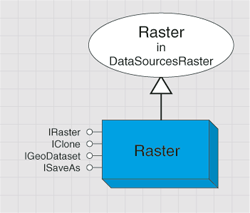
Because of the transient nature of Raster, any modifications made to this object will be lost when the object is released. Although the Raster object is always transient in nature, it must be associated with one or more raster bands, which provide a source for data to be read through the raster. As such, Raster is most easily understood as a vehicle to provide resampling, projection, and data type conversion from one or more raster bands to a desired output coordinate system. The modified Raster can be persisted to another raster dataset on disk or in a geodatabase using the ISaveAs or IRasterBandCollection interface.
The IRasterProps interface is used to control the properties of the raster, such as extent, width, height, spatial reference, pixel type, NoData value, and so on.
You can get the cell size of a raster. However, setting a cell size to a raster should be done by adjusting width, height, and the extent of the raster. If the height and/or width are changed, the cell size will be recalculated using the new height and width to divide the current raster extent. In this case, it will most likely result in a raster with non-square cell size. You can control whether you get a raster with square cell size by specifying a precalculated height and width.
The NoData value of a raster is represented as an array of values. This variant array of values has the pixel type of the raster and contains one NoData value for each band. This allows the different bands in the raster to contain a different NoData value. If there is no NoData value in the band, the value in the corresponding member of the array will be empty. Resampling sometime occurs when the properties of Raster are changed. The resampling can be set using the ResampleMethod property on the IRaster interface.
The following code example sets a new spatial reference (pNewSpatialReference) to Raster and persists to a file, assuming pRaster is obtained:
[C#] // Set the raster's resampling method and apply a spatial reference.
raster.ResampleMethod=rstResamplingTypes.RSP_BilinearInterpolation;
IRasterProps rasterProps=(IRasterProps)raster;
rasterProps.SpatialReference=spatialReference;
// Save the raster as a GRID.
ISaveAs saveAs=(ISaveAs)raster;
saveAs.SaveAs("MyRaster", rasterWorkspace, "GRID");
' Set the raster's resampling method and apply a spatial reference.
raster.ResampleMethod=rstResamplingTypes.RSP_BilinearInterpolation
Dim rasterProps As IRasterProps=CType(raster, IRasterProps)
rasterProps.SpatialReference=spatialReference

' Save the raster as a grid.
Dim saveAs As ISaveAs=CType(raster, ISaveAs)
saveAs.SaveAs("MyRaster", rasterWorkspace, "GRID")
A Raster object can create PixelBlock, and pixel value of the raster can be modified by a pixel filter using IPixelFilterOperation and persisted to a raster dataset using SaveAs. The pixel values of the Raster object can also be modified and written directly to the raster dataset using the IRasterEdit interface.
Raster can be displayed using a RasterLayer object, which is an object in the Carto library. Raster can also be cocreated. Cocreating a new raster results in an empty raster that is not useful until one or more bands are placed into the raster, providing data for the raster to read. Creating a new raster and populating it with the desired bands provides the most flexibility. Any time a band is added or removed from a raster, its default settings for spatial reference, extent, and cell size can be changed, and these default settings will be applied to the raster if they have not been previously set by the user.
Pixel blocks
The PixelBlock object contains a pixel array that can be read from a raster or a raster band. The PixelBlock object handles generic pixel arrays from any raster data source. This means it must be able to handle single and multiband data, as well as support different pixel types. To support different pixel types, PixelBlock transports pixels in a SafeArray, which has the ability to contain many different data types. To support multiple bands, or planes, of raster data, PixelBlock provides a separate array for each band in the raster. The PixelBlock object is shown in the following diagram:

The PixelBlock object can be created from both Raster and RasterBand. The size of the pixel block is required when creating a pixel block. Once specified, pixel block size cannot be changed. To read pixel values to the pixel block, the pixel location (in pixel space) in the raster band where the PixelBlock starts to read needs to be specified as shown in the following code example:
[C#] // Define the pixel block size.
IPnt size=new PntClass();
size.SetCoords(512, 512);
// Create the pixel block from a raster.
IPixelBlock pixelBlock=raster.CreatePixelBlock(size);
// Create the pixel block from a band.
IRawPixels rawPixels=(IRawPixels)rasterBand;
pixelBlock=rawPixels.CreatePixelBlock(size);
// Define the starting pixel in pixel space to read.
IPnt topLeft=new PntClass();
topLeft.SetCoords(0, 0);
// Read the pixel block from a band.
rawPixels.Read(topLeft, pixelBlock);
' Define the pixel block size.
Dim Size As IPnt=New PntClass()
Size.SetCoords(512, 512)

' Create the pixel block from a raster.
Dim pixelBlock As IPixelBlock=raster.CreatePixelBlock(Size)

' Create the pixel block from a band.
Dim rawPixels As IRawPixels=CType(rasterBand, IRawPixels)
pixelBlock=rawPixels.CreatePixelBlock(Size)

' Define the starting pixel in pixel space to read.
Dim topLeft As IPnt=New PntClass()
topLeft.SetCoords(0, 0)

' Read the pixel block from a band.
rawPixels.Read(topLeft, pixelBlock)
You can get the pixel values from the pixel block, modify the pixel values, and write the pixel block with the modified pixel values to RasterBand. If the pixel block is created from Raster, the modified pixel block can be written to a raster dataset using IRasterEdit.Write.
For small raster datasets, the pixel block can be the size of the entire dataset, which can usually be held in memory, and the starting pixel to read the pixel block can be (0,0). Larger rasters can be read in smaller pieces by creating a smaller PixelBlock and reading portions of the raster sequentially.
PixelBlockCursor and RasterCursor are the two objects that allow you to divide a large image into many pixel blocks and read them one by one. PixelBlockCursor is an enhanced object that reads pixel blocks from large images. You can loop through pixel blocks from RasterBand or Raster. When reading pixel blocks from Raster, the size of the pixel block is optimized automatically by the system according to the different raster formats from which the raster is created, and the location of the top-left corner of the next pixel block is returned each time a pixel block is read. When reading pixel blocks from RasterBand, the size of the pixel block needs to be defined.
Raster catalogs
RasterCatalog is a data type that only applies to raster catalogs in a geodatabase. RasterCatalog manages a collection of raster datasets as one entity, a special type of FeatureClass. This special type of feature class has a name field that stores the name of the raster dataset, a geometry field that stores the footprint (bounding box) of the raster dataset, and a raster field that stores pixel values of the raster dataset. It can also contain other fields, such as metadata. The RasterCatalog object is shown in the following diagram:
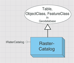
The value stored in the raster field is called RasterValue. RasterValue contains RasterDataset and RasterStorageDef. The raster field has a spatial reference that is applied to all raster values and is defined using RasterDef. The property of the geometry field is defined by GeometryDef. The footprints of the raster datasets stored in the geometry field are automatically managed, populated, and spatially indexed by the geodatabase. The spatial references of the raster and geometry fields are recommended to be same.
In addition to defining the spatial reference for the raster column, RasterDef also defines how the raster values are managed in the raster catalog. A managed raster catalog stores raster values in the raster catalog, while an unmanaged raster catalog stores only the paths to the raster datasets, and those raster datasets reside in a file system. A raster catalog in an ArcSDE geodatabase is always managed, while a raster catalog in a personal geodatabase can be unmanaged, which means the raster datasets in the raster catalog do not reside in the personal geodatabase, but in a file system.
The RasterStorageDef object defines how a raster value is stored in an ArcSDE geodatabase. You can define the tile size, cell size, and origin of the raster value. You can also define the compression type as well as the resampling method of pyramid building.
As a subclass of FeatureClass, RasterCatalog consists of rows. The feature in each row is a RasterCatalogItem, a type of feature. RasterCatalog operates the same way as a FeatureClass when accessing or updating the raster datasets in the RasterCatalog (for example, enumeration of the raster datasets in a RasterCatalog is accomplished by acquiring a standard FeatureCursor on the RasterCatalog). Insert and update can be achieved by an insert cursor or an update cursor.
To create a raster catalog, create an empty raster catalog, which is described in the workspace section, then add rows that contain raster values to the raster catalog.
The following code example shows one way to load a raster dataset to a raster catalog:
[C#] // Create a raster value from an open raster dataset.
IRasterValue rasterValue=new RasterValueClass();
rasterValue.RasterDataset=rasterDataset;
// Cast an open raster catalog to the IFeatureClass interface.
IFeatureClass featureClass=(IFeatureClass)rasterCatalog;
// Create a row, set the raster value, and call store.
IFeature feature=featureClass.CreateFeature();
feature.set_Value(rasterCatalog.RasterFieldIndex, rasterValue);
feature.Store();
' Create a raster value from an open raster dataset.
Dim rasterValue As IRasterValue=New RasterValueClass()
rasterValue.RasterDataset=rasterDataset

' Cast an open raster catalog to the IFeatureClass interface.
Dim featureClass As IFeatureClass=CType(rasterCatalog, IFeatureClass)

' Create a row, set the raster value, and call store.
Dim feature As IFeature=featureClass.CreateFeature()
feature.Value(rasterCatalog.RasterFieldIndex)=rasterValue
feature.Store()
The following code example shows how to get the raster dataset stored in a raster catalog item with an ObjectID of 1:
[C#] IFeatureClass featureClass=(IFeatureClass)rasterCatalog;
IRasterCatalogItem rasterCatalogItem=(IRasterCatalogItem)featureClass.GetFeature(1)
;
IRasterDataset rasterDataset=rasterCatalogItem.RasterDataset;
Dim featureClass As IFeatureClass=CType(rasterCatalog, IFeatureClass)
Dim rasterCatalogItem As IRasterCatalogItem=CType(featureClass.GetFeature(1), IRasterCatalogItem)
Dim rasterDataset As IRasterDataset=rasterCatalogItem.RasterDataset
RasterCatalog can be displayed using the GdbRasterCatalogLayer object from the Carto library.
Metadata
The metadata subsystem contains the objects for creating, copying, editing, importing, exporting, and synchronizing metadata for datasets, maps, layers, geoprocessing tools, and other supported objects. The metadata objects are detailed in the following diagram:

Most supported objects in ArcGIS can have metadata. For datasets accessed using an OLE DB, ArcSDE 3, or an SDE for Coverages database connection, you cannot create metadata nor read metadata that already exists. For all other objects, if you have write permission or have been granted edit permissions, ArcCatalog will, by default, create and update the metadata automatically when you view it on the Metadata tab (not when the properties or content of the dataset are changed). This process is referred to as synchronization; the Catalog extracts properties from the dataset, calculates values if necessary, then stores the information in the dataset’s metadata.
Metadata is stored in an XML document. For file-based datasets, the XML document resides in an appropriately named XML file on the file system. For example, a shapefile’s metadata is stored in a file that has the same name as the shapefile, such as myShapefile.shp.xml. A coverage’s metadata is stored in a metadata.xml file within the coverage directory.
Within geodatabases, metadata is stored in the geodatabase system tables as either a binary large object (BLOB) (9.3 geodatabases and earlier) or an XML property set serialized into an XML column (10 and later).
To manage metadata with ArcObjects, you need basic knowledge of XML and XPath to manipulate the metadata elements.
You can get the value of a specific metadata element using the IXmlPropertySet2.GetXML method and change the value of the element using the SetPropertyX method.
Plug-in data sources
The plug-in data source subsystem contains objects that allow you to create your own read-only data sources for the geodatabase and for applications to access them. The plug-in data source objects are detailed in the following diagram:

ArcGIS deals with several read-only data sources, such as StreetMap, CAD, and the smart data compression (SDC) format used by RouteMap IMS. The method by which ArcGIS handles some of these data sources has been exposed to developers—you can provide ArcGIS support for your own data formats by implementing a plug-in data source.
A plug-in data source integrates a new data format completely into ArcGIS, albeit in a read-only manner. You can browse, preview, and manage the data in ArcCatalog. You can select, render, query, label, and join the data in ArcMap. You can also program with the data source using normal geodatabase interfaces such as IWorkspace and IFeatureClass.
There are some limitations: only tables, feature classes, and feature datasets are supported; you cannot integrate plug-in data sources with geodatabase objects, such as relationship classes and geometric networks. Additionally, no direct support is provided for dataset manipulation—for example, copy, delete, rename, new, import, or export.
Network dataset
A network dataset is a collection of junction, edge, and turn elements that are connected and model how real life entities are connected. The network dataset is used as the input to the solvers of the Network Analyst objects to solve graph theoretic problems. The junctions, edges, and turns of a network dataset are generated from simple features in network sources. The network dataset contains attributes to represent cost impedances, restrictions, and hierarchy values of the network elements.
The NetworkDataset object is used to access the contents of the network dataset. Its main interface, INetworkDataset, allows you to inspect the sources, attributes, and other properties of the network dataset. The INetworkBuild interface allows you to make changes to the source and attribute definitions of the network dataset, as well as regenerate the elements of the network dataset from its sources.
The INetworkQuery interface allows you to query for specific junction, edge, and turn elements in the network dataset. The INetworkQuery interface is also the place to create a NetworkForwardStar object for querying repeatedly for adjacent elements in the network. NetworkForwardStar is the basis object for traversing a network to solve a graph theoretic problem. The INetworkForwardStarSetup interfaces allows you to customize the NetworkForwardStar object to limit which elements are returned during the query based on restrictions, barriers, hierarchy, and backtrack settings.
Once you query for an element in the network, you can use the INetworkElement interface to access properties of the element, such as its element ID, the ID of the source that generated that element, and the attribute values for that element. The INetworkJunction, INetworkEdge, and INetworkTurn interfaces allow access to properties of the element that are specific to a particular element type.
The DENetworkDataset object is the data element representation of a network dataset. Its main interface, IDENetworkDataset, allows access to the network dataset's sources, attributes, and other properties. IDENetworkDataset also allows you to modify the data element. However, changes made to the data element are not applied to the actual network dataset until INetworkBuild.UpdateSchema() is called.
The network source objects describe a network source in the network dataset. Each object implements INetworkSource, allowing you to view the properties of that source. The object can implement a source-specific interface, such as IEdgeFeatureSource or IJunctionFeatureSource, which allows you to view and set the connectivity settings for that source.
A source can also have specifications for which fields on the source generate driving directions. These settings are accessed by the INetworkSourceDirections interface.
The INetworkAttribute interface accesses the properties of a network attribute. For network attributes in geodatabase and shapefile network datasets, the IEvaluatedNetworkAttribute interface specifies which evaluators are associated with the attribute. An evaluator is an object that determines how the attribute values of a network element are calculated. The following evaluators are available in ArcGIS:
- NetworkConstantEvaluator—Assigns a constant attribute value to all elements generated by the given source.
- NetworkFieldEvaluator—Assigns attribute values from the values of a single field on the source feature class, or from a mathematical expression involving values from multiple fields.
- NetworkFunctionEvaluator—Derives attribute values by applying a multiplicative or comparative function to the values from another network attribute.
- NetworkGlobalTurnDelayEvaluator—Assigns attribute values for turn elements based on the turn deflection angle and road classes of the streets at the intersection.
- NetworkScriptEvaluator—Calculates the attribute value from a script involving the properties of each network element.
You can also implement your own evaluator by creating objects that implement INetworkEvaluator, INetworkEvaluator2, and INetworkEvaluatorSetup.
For further information see:
How to create a network datasetHow to create a multimodal network dataset
How to open a network dataset
How to access source features referenced by a network dataset
How to programmatically traverse a street network
Sample: Import signposts
Sample: Selection restriction evaluator
Sample: Subset network evaluators
Representation class
The representation class subsystem contains objects that allow you to create and manage representation classes for a feature class within a geodatabase.
A RepresentationClass object is a feature class enabled with cartographic representation capabilities useful for symbolizing features in the geodatabase and to edit the appearance of individual features on your maps. A representation class is also called a feature class representation. The representation information is stored in the geodatabase and can be overridden for individual features in places where graphic conflict arises or fine tuning of symbology is required. A feature class can have multiple representation classes associated with it, giving you the ability to produce multiple maps from a single geodatabase. The representation class, however, is always associated with the single feature class to which it belongs.
Enabling representations on a feature class results in the addition of two new fields: RuleID (fieldtype long to store RepresentationRule ID value) and Override (fieldtype BLOB to store feature-specific override information). Deleting a representation class results in the deletion of these two fields (except when the feature class is in a DB2 ArcSDE geodatabase).
A representation class implements the IRepresentationClass interface, which contains properties and methods to manipulate the attributes of the representation class and/or to retrieve individual representations. The IDataset and ISchemaLock interfaces are also implemented.
RepresentationWorkspaceExtension is a workspace extension used for the creation and management of representation classes. The IRepresentationWorkspaceExtension interface is implemented by RepresentationWorkspaceExtension. You can use the CreateRepresentationClass method to create a new representation class by providing a feature class as input. This method takes other input parameters that are more specific to the representation class, such as RuleIDFldName (representation rule ID field name), OverrideFldName (override field name), RequireShapeOverride, and RepresentationRules. The OpenRepresentationClass method is useful to get a reference to an existing representation class by providing its name as an input parameter. When working with an ArcSDE geodatabase, the fully qualified name is not required to open the representation class, as the name is qualified using the currently connected user for the workspace.
This following code example opens a representation workspace extension for a workspace:
[C#] IWorkspaceExtensionManager extensionManager=(IWorkspaceExtensionManager)workspace;
UID uid=new UIDClass();
uid.Value="esriGeodatabase.RepresentationWorkspaceExtension";
IRepresentationWorkspaceExtension repExtension=(IRepresentationWorkspaceExtension)
extensionManager.FindExtension(uid);
Dim extensionManager As IWorkspaceExtensionManager=CType(workspace, IWorkspaceExtensionManager)
Dim uid As UID=New UIDClass()
uid.Value="esriGeodatabase.RepresentationWorkspaceExtension"
Dim repExtension As IRepresentationWorkspaceExtension=CType(extensionManager.FindExtension(uid), IRepresentationWorkspaceExtension)
The following code example creates a new representation class on a feature class:
The RepresentationRules property is empty since no representation rules have been added.
IRepresentationRules rules=new RepresentationRules();
IRepresentationClass repClass=repExtension.CreateRepresentationClass(featureClass,
    "Cities_Rep", "My_RuleID", "My_Override", false, rules, null);
Dim rules As IRepresentationRules=New RepresentationRules()
Dim repClass As IRepresentationClass=repExtension.CreateRepresentationClass(featureClass, "Cities_Rep", "My_RuleID", "My_Override", False, rules, Nothing)
Representation rules
Representation rules are rules that govern the symbology of a representation class. Every representation class consists of a set of representation rules. You can either create a new rules object from scratch or copy existing rules from another representation class. It is necessary to have a reference to the rules while creating a new representation class using the IRepresentationWorkspaceExtension.CreateRepresentationClass method. The RuleID field will contain the ID of the representation rule, which is used by feature representations while they are drawn on a map. The IRepresentationRules interface is used to manage the collection of representation rules. After getting a reference to an existing rules object, the first step is to use the Reset and Next methods to set the collection to the beginning and start retrieving each rule, one after another, along with their unique ID values. This ID value can be used to retrieve the Index, Name, and Rule properties. You can either expand or contract the collection by adding or deleting rules using the Add and Remove methods. The RemoveAll method removes every rule in the collection.
Each rule is a combination of a BasicMarkerSymbol and MarkerPlacements, BasicLineSymbol, BasicFillSymbol, and/or GeometricEffects, which are objects in the Display library.
Representations are cartographic depictions of geographic features and are present in a representation class. When creating a feature class representation, each feature will be associated with a feature representation. A representation object supports the IRepresentation interface. Using this interface in conjunction with the IOverride interface gives you the capability to override attribute and shape properties of individual representations.
The following code example takes RepresentationClass and a feature as input parameters and returns the associated feature representation. MapContext is an object in the Display library.
[C#] // Create a map context using a feature class' spatial reference.
IGeoDataset geoDataset=(IGeoDataset)featureClass;
IMapContext mapContext=new MapContextClass();
mapContext.Init(geoDataset.SpatialReference, 10000, geoDataset.Extent);
// Get a feature with a known ObjectID from the feature class.
IFeature feature=featureClass.GetFeature(1);
// Get the feature's representation from the representation class.
repClass.GetRepresentation(feature, mapContext);
' Create a map context using a feature class' spatial reference.
Dim geoDataset As IGeoDataset=CType(featureClass, IGeoDataset)
Dim mapContext As IMapContext=New MapContextClass()
mapContext.Init(geoDataset.SpatialReference, 10000, geoDataset.Extent)

' Get a feature with a known ObjectID from the feature class.
Dim feature As IFeature=featureClass.GetFeature(1)

' Get the feature's representation from the representation class.
repClass.GetRepresentation(feature, mapContext)
