Summary
Creates a new feature class containing geodetic line features constructed based on the values in an x-coordinate field, y-coordinate field, bearing field, and distance field of a table.
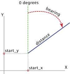
Illustration

Usage
If you use text files and .csv (comma-separated value) files as input, make sure that they follow the file structure specified in About tabular data sources.
Each geodetic line is constructed using a particular set of field values representing the x and y coordinates of a starting point, distance from the starting point, and bearing angle measured from North. These fields and values will be included in the output.
A geodetic line is a curve on the surface of the earth. However, a geodetic line feature is not stored as a parametric (true) curve in the output, but as a densified polyline representing the path of the geodetic line. If the length of a geodetic line is relatively short, it may be represented by a straight line in the output. As the length of the line increases, more vertices are used to represent the path.
When the output is a feature class in a file geodatabase or a personal geodatabase, the values in the Shape_Length field are always in the units of the output coordinate system specified by the Spatial Reference parameter; and they are the planar lengths of the polylines. To measure a geodesic length or distance, use the ArcMap Measure tool; make sure to choose the Geodesic, Loxodrome, or Great Elliptic option accordingly before taking a measurement.
Syntax
BearingDistanceToLine_management (in_table, out_featureclass, x_field, y_field, distance_field, {distance_units}, bearing_field, {bearing_units}, {line_type}, {id_field}, {spatial_reference})| Parameter | Explanation | Data Type |
in_table | The input table that can be a text file, CSV file, Excel file, dBASE table, or geodatabase table. | Table View |
out_featureclass | The output feature class containing densified geodetic lines. | Feature Class |
x_field | A numerical field in the input table containing the x coordinates (or longitudes) of the starting points of lines to be positioned in the output coordinate system specified by the spatial_reference parameter. | Field |
y_field | A numerical field in the input table containing the y coordinates (or latitudes) of the starting points of lines to be positioned in the output coordinate system specified by the spatial_reference parameter. | Field |
distance_field | A numerical field in the input table containing the distances from the starting points for creating the output lines. | Field |
distance_units (Optional) | The units for the values in the distance_field.
| String |
bearing_field | A numerical field in the input table containing bearing angle values for the output line rotation. The angles are measured clockwise from North. | Field |
bearing_units (Optional) | The units of the values in the bearing_field.
| String |
line_type (Optional) | The type of geodetic line to construct.
| String |
id_field (Optional) | A field in the input table; this field and the values are included in the output and can be used to join the output features with the records in the input table. | Field |
spatial_reference (Optional) | The spatial reference of the output feature class. You can specify the spatial reference in several ways:
| Spatial Reference |
Code sample
BearingDistanceToLine example (stand-alone script)
Converts bearing and distance info into a line.
# Import system modules
import arcpy
from arcpy import env

# Local variables
input_table = r"c:\workspace\LOBtraffic.dbf"
output_fc = r"c:\workspace\SOPA.gdb\lob_traf001"

#BearingDistanceToLine
arcpy.BearingDistanceToLine_management(input_table, output_fc, "X", "Y",
"NAUTICAL_MILES", "azim", "DEGREES", "GEODESIC","recnum")
Environments
Licensing information
- ArcGIS for Desktop Basic: Yes
- ArcGIS for Desktop Standard: Yes
- ArcGIS for Desktop Advanced: Yes